Power Distribution Board Construction
Now that the heatsticks are done, we need a way to get power to them. Ordinary residential wiring can only handle one heatstick per circuit. Even if multiple circuits are available in your brewing room, they’re probably scattered throughout and relatively inaccessible. Switching heatsticks on/off by unplugging them is also inconvenient, especially when your wort is threatening to boil over and the plug you need to pull is on the other side of the room.
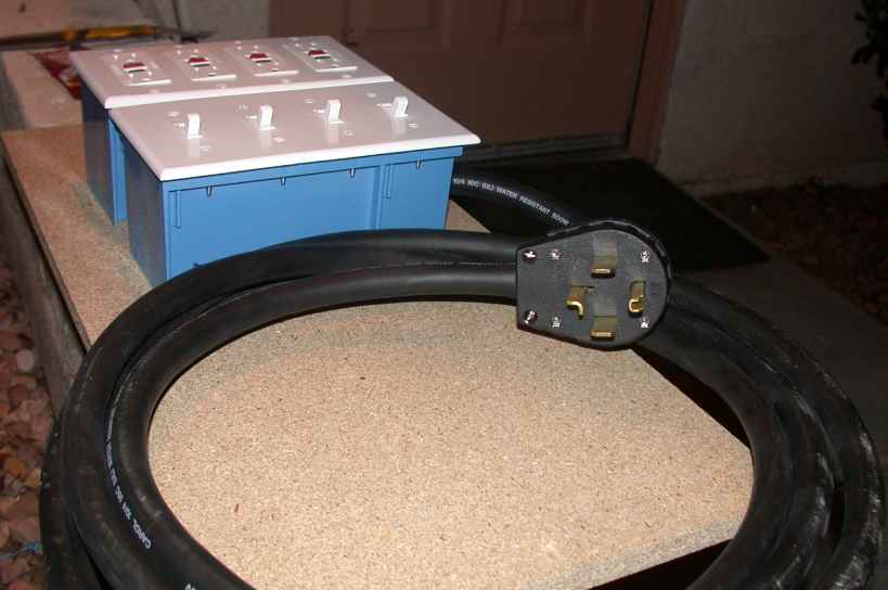
This project takes a 240-volt 30-amp circuit (what your clothes dryer most likely uses) and splits it out to four 120-volt 15-amp circuits that can each power one heatstick (or other brewing equipment, like a swamp-cooler pump feeding your wort chiller). Each circuit has a GFCI outlet on the end, so that if something should go wrong with a heatstick, the outlet will trip and you’ll avoid a nasty surprise.
If you’re building 2-kW heatsticks, you’ll want to upgrade this project to provide 20-amp outlets. A 240-volt 50-amp circuit (what an electric stove most likely uses) will supply enough power. If you’re putting in a new circuit for use with your heatsticks, a 40-amp breaker (instead of 50) might be a good idea. Upgraded parts are called out in the partlist where needed. Note that the photos show a board being built for 1.5-kW heatsticks.
You’ll need the following parts:
- two plastic 4-gang old work wiring boxes (“old work” means a box that you’d stick through a hole in an existing wall for mounting; it has some swing-out plastic tabs attached to screws that we’ll remove for our use)
- four 120-volt 15-amp (for 1.5-kW use) or 20-amp (for 2-kW use) GFCI outlets (don’t cheap out and get regular outlets…for safety’s sake, spend the little bit of extra money)
- four 15-amp (for 1.5-kW use) or 20-amp (for 2-kW use) SPST (single-pole single-throw) light switches
- 4-gang cover plates for the GFCI outlets and the switches
- a plug to match your outlet (This page shows the different types of plugs and receptacles. Types 14-30P (1.5-kW heatsticks only), 14-50P (1.5- or 2-kW), and 14-60P (ditto) would be easiest and safest to get going. Types 10-30P (1.5-kW only) and 10-50P (1.5- or 2-kW) might work if you tie ground to neutral, but I’m not sure if this would be considered safe practice and therefore can’t recommend it at this time. Types 6-30P, 6-50P, and 2-30P will definitely not work because they don’t provide a neutral connection and can therefore only provide 240V.)
- enough 10/4 (for 1.5-kW use) or 8/4 (for 2-kW use) SOOW appliance cord to reach from the outlet to your brewing area, with a few feet extra (this is a thick rubber-jacketed cord with four wires inside and offers a sufficient insulation breakdown voltage (600V) to be usable on a 240V circuit)
- 15′ of 14/2 (for 1.5-kW use) or 12/2 (for 2-kW use) Romex (or equivalent) solid-conductor cable (live and neutral have their own insulation in this cable, but ground doesn’t)
- four three-terminal blocks (you’ll find these near the circuit breakers, as they normally go inside breaker boxes)
- a package of 7″ zip ties
- some #8 sheet-metal screws in 1/2″ and 3/4″ lengths
- a 1×2′ piece of 3/4″ particle board to serve as a base
For tools, you’ll need screwdrivers, wire cutters, wire strippers, a razor blade or sharp knife, long-nose pliers, a round file, and a drill and bits.
Disclaimer: I shouldn’t have to put this in here, but if I didn’t and some numb-nuts got himself killed while trying to assemble or use this device, his next of kin might hire an ambulance chaser to sue me into oblivion. Since we haven’t yet heeded Shakespeare’s advice to kill all the lawyers, take heed: This project involves wiring parts together that will connect to a high-power electrical circuit (240 volts AC at 30 amps or more). If you don’t exercise sufficient care in assembly, testing, and use, you could zap yourself. Construction is fairly simple, but if you have any doubts about your electrical-wiring prowess, find somebody who is, or find another homebrew construction project that doesn’t involve electricity. I’m not responsible for your errors; if you break something, you own both pieces.
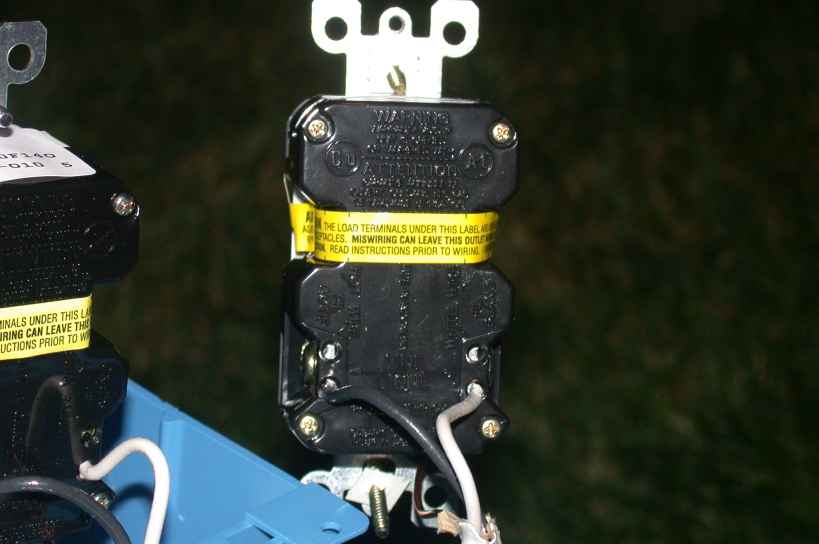
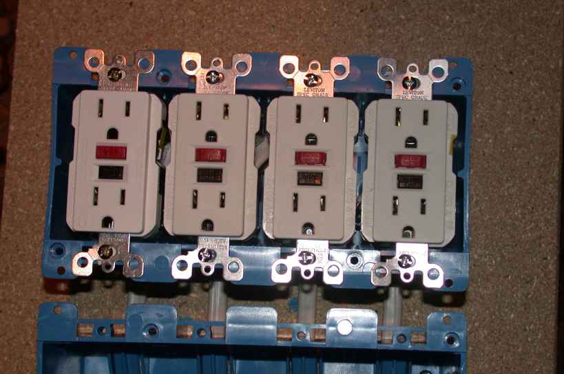
Start by cutting four 2′ lengths of Romex. On each, strip back 3″ of the outer jacket and 1/2″ of the insulation on the live (black) and neutral (white) wires. Attach the wires to the corresponding terminals on a GFCI outlet as shown (neutral goes to the “white” or “silver” screw, ground goes to the green screw). Two 90° bends a short distance apart on the end of each ground wire will provide a secure attachment, while the live and neutral wires will probably go into holes in the back provided for that purpose. Click any image for a closer view:
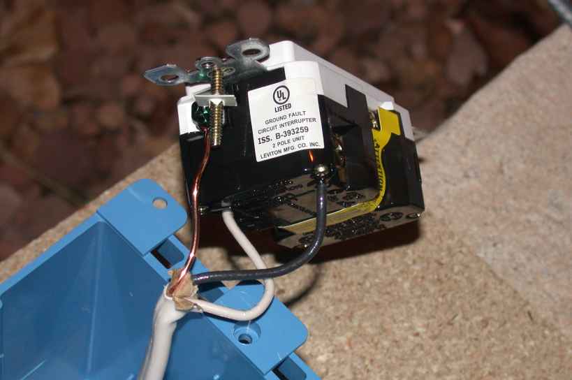
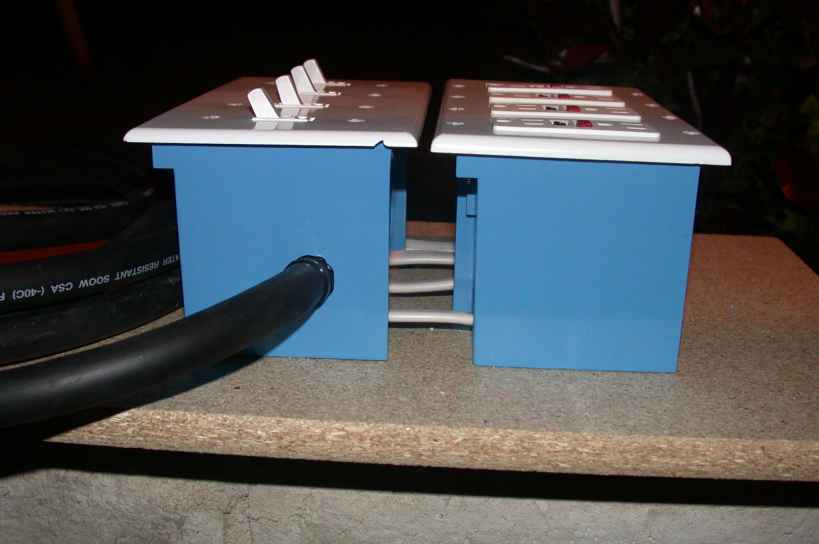
Feed the cables out one box and into the other, keeping the lengths in each box approximately the same. The boxes will need to be mounted about an inch apart, so keep that in mind. Bend the outlets out of the way so you’ll be able to screw in the outlet box:
Use four of the 1/2″ screws to secure the outlet box to the board. Use a 3/32″ bit to drill pilot holes:
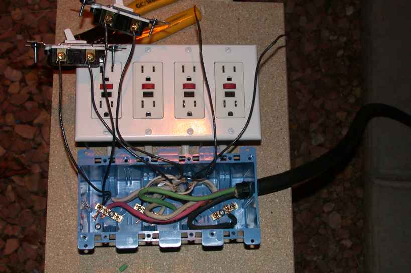
Screw the outlets down into the box, carefully folding the cable underneath so it doesn’t get pinched:
In the switch box, use four 3/4″ screws to secure the terminal strips as shown. For added mounting strength, a couple of 1/2″ screws elsewhere in the box would be a Good Thing:
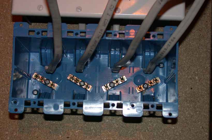
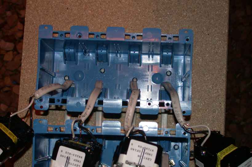
Strip back maybe 6″ of the outer jackets. Pair up the ground wires (the bare wires) from the left two positions and screw them to the #3 terminal block (third over from the left). Do the same with the ground wires from the right two positions. These need to be routed away from the other blocks because the wires aren’t insulated. Strip 1/2″ of insulation off the neutral wires (the white wires) and connect them to the #2 terminal block (second over from the left) in a similar manner:
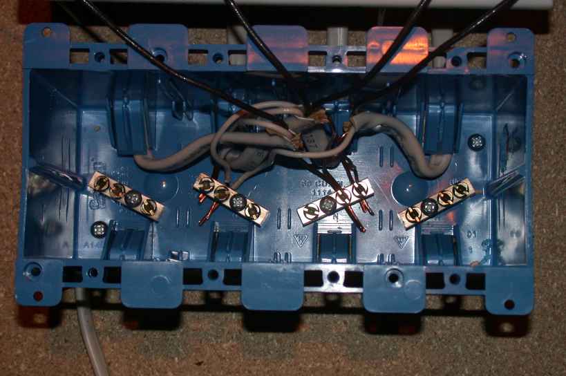
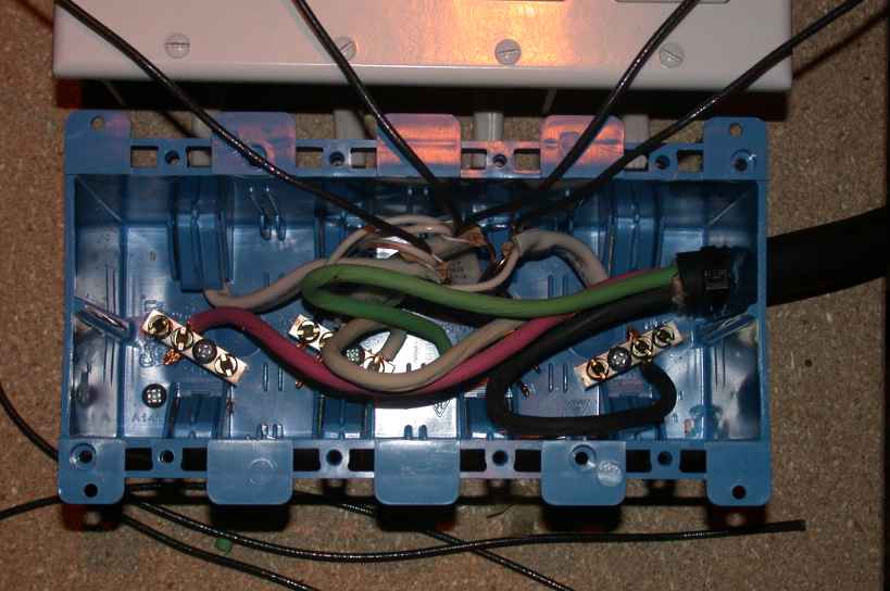
Carefully drill a 5/8″ hole in the right side of the switch box (a spade bit works well here); enlarge it with a file until the power cord just passes through. Remove 9″ of the outer jacket on the power cord and cut out the paper separators. Feed the cable into the box and secure it inside and outside with zip ties. Strip off 1/2″ of insulation from each wire and connect one wire to each block in this left-to-right order: red, white, green, black:
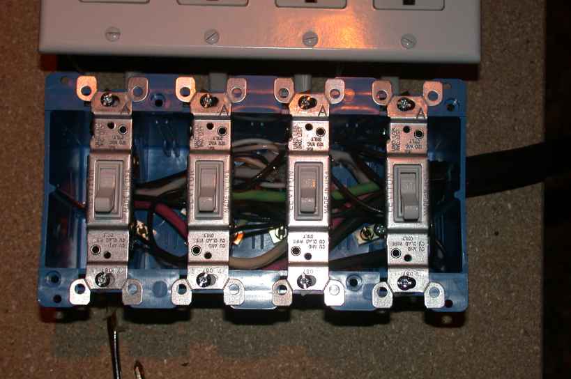
Cut a 3′ piece of Romex. Remove some of the outer jacket, grab the black wire with pliers, and pull it out of the jacket. Cut the wire into four equal lengths. Strip 3/4″ of insulation off of each end, as well as on the remaining wire ends in the box. For each of the left two circuits, connect a wire from the box and one of the loose wires to a switch. Connect the other ends of the loose wires to one terminal on the #1 block (the one with the red wire in it):
Repeat for the right two circuits, with the loose ends connected to a terminal on the #4 block (the one with the black wire in it).
Carefully fold the wires into the box and screw the switches down:
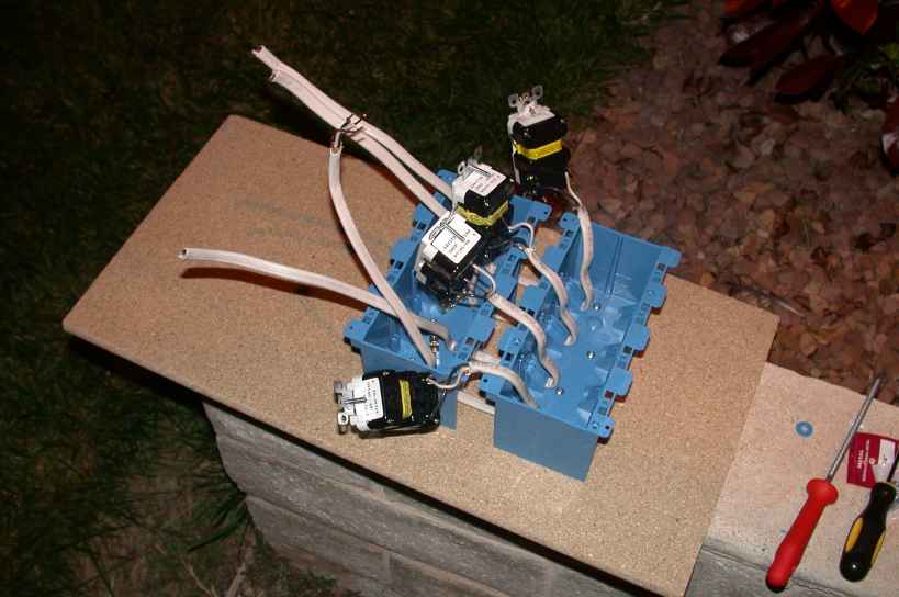
Install the cover plates with the screws included with each. Install the plug on the end of the power cord according to the directions that should’ve been packaged with it. When you’re done, you should have something that looks like this:

To test it, plug it in, flip the switches on, and reset all the GFCIs (they come pre-tripped and won’t reset if the wiring is screwed up). If you plug a lamp in, it should light up. If you plug a heatstick in, it should get hot.
The final part of the series includes “action shots” of the heatsticks and power distribution board at work on their inaugural brew (an ESB that I hope is reasonably close to Fuller’s).