Hundreds of parents showed up to the Vail [AZ?] School Board meeting to demand the board make masks optional. The board didn’t want to hear it so they walked out of the meeting before it even began. So the parents, under Robert’s Rules of Order, voted in a new school board. Then, the new members voted to end the mask requirement in Vail Schools. The old school board members revealed exactly who they are and that includes GOP LD 10 Chairman, Chris King.
The link to Rumble came from a radio station in Tucson, so I’m guessing the “Vail” mentioned above is the one in Arizona, not the one in Colorado. Vail, AZ, is maybe 15 or so miles southeast of Tucson.
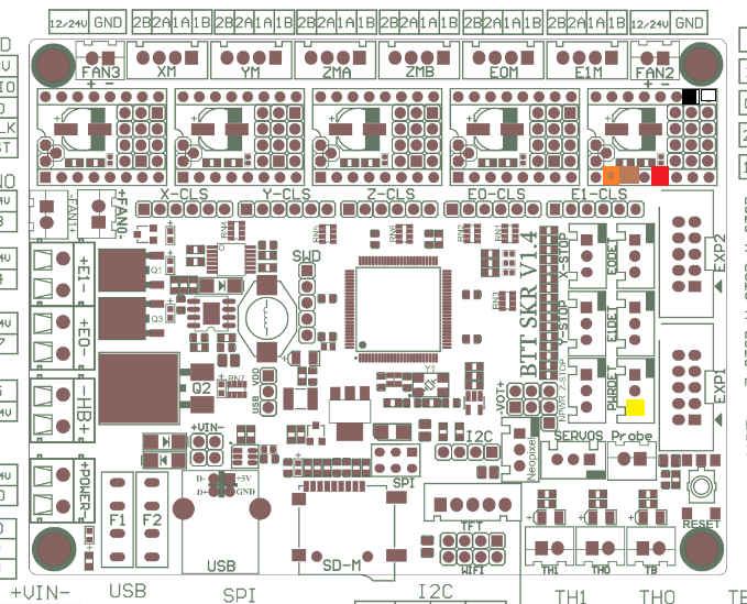
I wanted to upgrade one of my 3D printers to make it capable of printing with high-temperature materials. One of the things needed to pull that off is to replace the usual hotend thermistor (which maxes out around 280°C) with either a thermocouple (which can go into the thousands of degrees) or a platinum RTD (which, as packaged for printers, can usually go to 500° or so). Either of these requires additional electronics to make the device compatible; for a PT100 RTD, the device in question is a little board with a MAX31865 on it, which converts the small change in resistance of the RTD to a digital readout over SPI.
There is a guide to getting all this stuff working, but it seems unnecessarily involved while not providing all of your options. What follows is a simpler explanation that will get you up and running.
(I assume that you’re running the bugfix-2.0.x branch of Marlin, and that your printer has a single hotend with a thermistor that you want to replace with an RTD. For my upgrade, I also replaced the aluminum heater block with a nickel-plated copper block. I also have a 60W heater on order, as the 40W heater I’ve been using is having a hard time maintaining temperature with the blower running. Further, I assume that you’re using Trinamic 2130 or 5160 drivers and that you’re using SPI to configure them…we’re going to share that SPI connection. We’ll tap into most of the SPI signals at the E1 connector. If you have a second extruder, you might want to build something like this adapter.)
Hardware Configuration
When the parts arrive, you’ll most likely need to solder connectors onto the MAX31865 board. They should be in the bag with the board; assembly is self-explanatory. There are also a couple of jumper pads that need to be soldered together to put the chip in 2-pin mode.
You’ll also want to make a cable to connect to the SKR 1.4 Turbo. It should have a six-pin female Dupont connector on the MAX31865 end. The SKR end should have six one-pin Dupont connectors: one female (for the CS signal, along one edge of the cable if you’re using ribbon cable) and the rest male. Let’s say you’re using the same color coding that I used, based on the cables I had laying around:
MAX31865 pin
color
signal
SKR connection type
SKR connection pin
2
white
GND
male
E1, pin 8
3
black
VDD
male
E1, pin 9
4
brown
SCK
male
E1, pin 3
5
red
SDO
male
E1, pin 5
6
orange
SDI
male
E1, pin 2
7
yellow
CS
female
PWRDET, pin 3
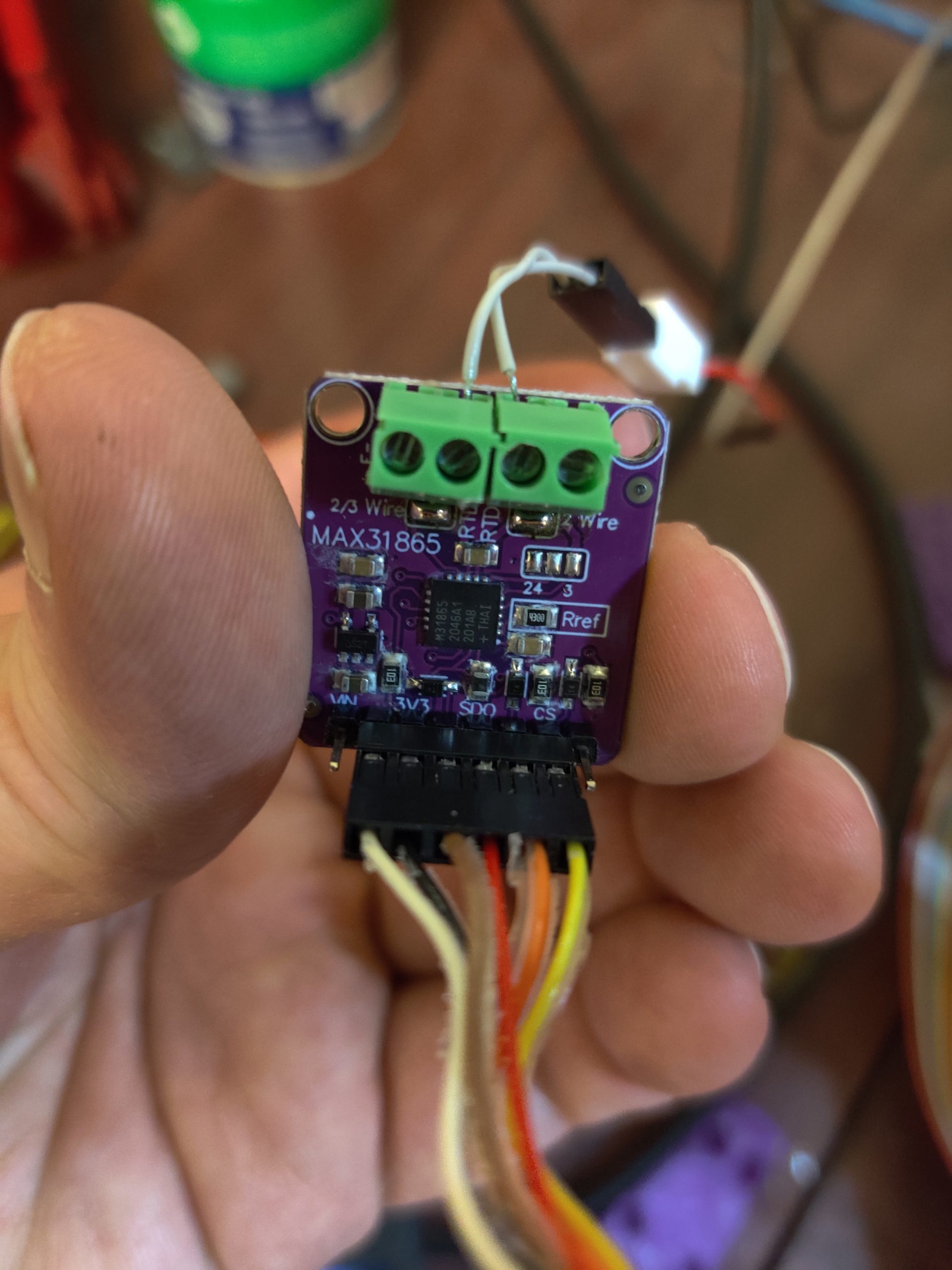
Pins 1 (5V) and 8 (RDY) on the MAX31865 aren’t used, as it and the printer motherboard are both 3.3V devices. A color-coded map of connections to the SKR 1.4 Turbo follows:
The RTD should be connected to the middle two terminals on the side opposite the SPI connector. Mine came with a 2-pin Molex connector, so I just knocked together a little adapter with a Dupont connector and some wire. Take note that the 6-pin connector is centered on the board’s 8-pin connector.
Software Configuration
With the hardware sorted, we now turn to configuring Marlin. Most of the changes can go in the thermal-settings section of Configuration.h.
#define TEMP_SENSOR_0 -5
#define MAX31865_MOSI_PIN TMC_SW_MOSI
#define MAX31865_MISO_PIN TMC_SW_MISO
#define MAX31865_SCK_PIN TMC_SW_SCK
#define MAX6675_SS_PIN POWER_LOSS_PIN // MAX31865_CS_PIN is copied from this
#define MAX31865_SENSOR_OHMS_0 100
#define MAX31865_CALIBRATION_OHMS_0 430
#define MAX31865_USE_60HZ // omit this if you're in a 50-Hz part of the world
#define MAX31865_USE_AUTO_MODE
#define MAX31865_USE_READ_ERROR_DETECTION
Trinamic drivers on the SKR 1.4 Turbo use software SPI, so that’s what we end up selecting here. MOSI (SDI), MISO (SDO), and SCK pins are set to the same ones the Trinamic drivers use, while the CS pin is set to a pin that we’re not using so we can still install a second extruder in the future. Any pin that doesn’t have a pullup or pulldown is OK…I’m using the pin on the PWRDET connector.
To use hardware SPI, the MAX31865_*_PIN entries don’t need to be defined. Just define MAX6675_SS_PIN, which is copied internally to MAX31865_CS_PIN. From what I’ve read, if there are multiple hardware SPI buses, the driver will default to using one of them and there’s no way to choose the other. I haven’t had a chance to verify this behavior.
If you’re using a PT1000 instead of a PT100, the MAX31865_*_OHMS values both need to be multiplied by 10 and you need to replace the Rref resistor on the MAX31865 board with a 4.3kΩ part (stock is a 430Ω 0.1% 0805 SMD resistor).
There’s also a change needed in Adafruit_MAX31865.h (in my source tree, it’s in .pio/libdeps/LPC1769/Adafruit MAX31865 library). Line 49 (or thereabouts) looks like this:
#if (ARDUINO >= 100)
ARDUINO isn’t defined by the LPC176x Arduino framework; instead, it needs to look at ARDUINOLPC:
#if (ARDUINOLPC >= 100)
Without this change, you’ll get compile errors saying that WProgram.h can’t be found.
Instead of the above, there’s an updated driver for the MAX31865 that also fixes some serious performance issues with the original. Go into ini/features.ini and look for this line:
With these changes made, compile, write the firmware.bin file that’s produced to a MicroSD card, pop it into the slot on the SKR, and hit Reset (or power it up).
Other Notes
I’ve noticed that the Marlin UI (on one of the cheap 128×64 graphical LCDs) is a bit laggy, but the printer is otherwise running properly. Switching from the software SPI used for Trinamic drivers to one of the hardware SPI channels might fix that. If I’m not mistaken, there are two: one is brought out on the EXP2 connector for cheap 128×64 graphical LCDs like mine (to go to the SD-card slot on such devices), and another goes to the onboard MicroSD slot and is also available on an SPI header adjacent to that slot. Changing MAX31865_MOSI_PIN, MAX31865_MISO_PIN, and MAX31865_SCK_PIN to use those other channels ought to do the trick (and leave out MAX31865_USES_SW_SPI if you do that).
Display lag and other issues were the result of lengthy delays hardcoded in the Adafruit driver. The zeleps fork of that driver appears so far to have fixed that problem. I currently have the MAX31865 board sharing hardware SPI with the onboard MicroSD slot, but sharing it with the display or with Trinamic drivers should work as well, whether with hardware or software SPI.
I’ve also given some thought to trying ReprapFirmware, now that you don’t need to fork over the big bucks for a Duet to run it. How this setup would cooperate with that, I don’t know.
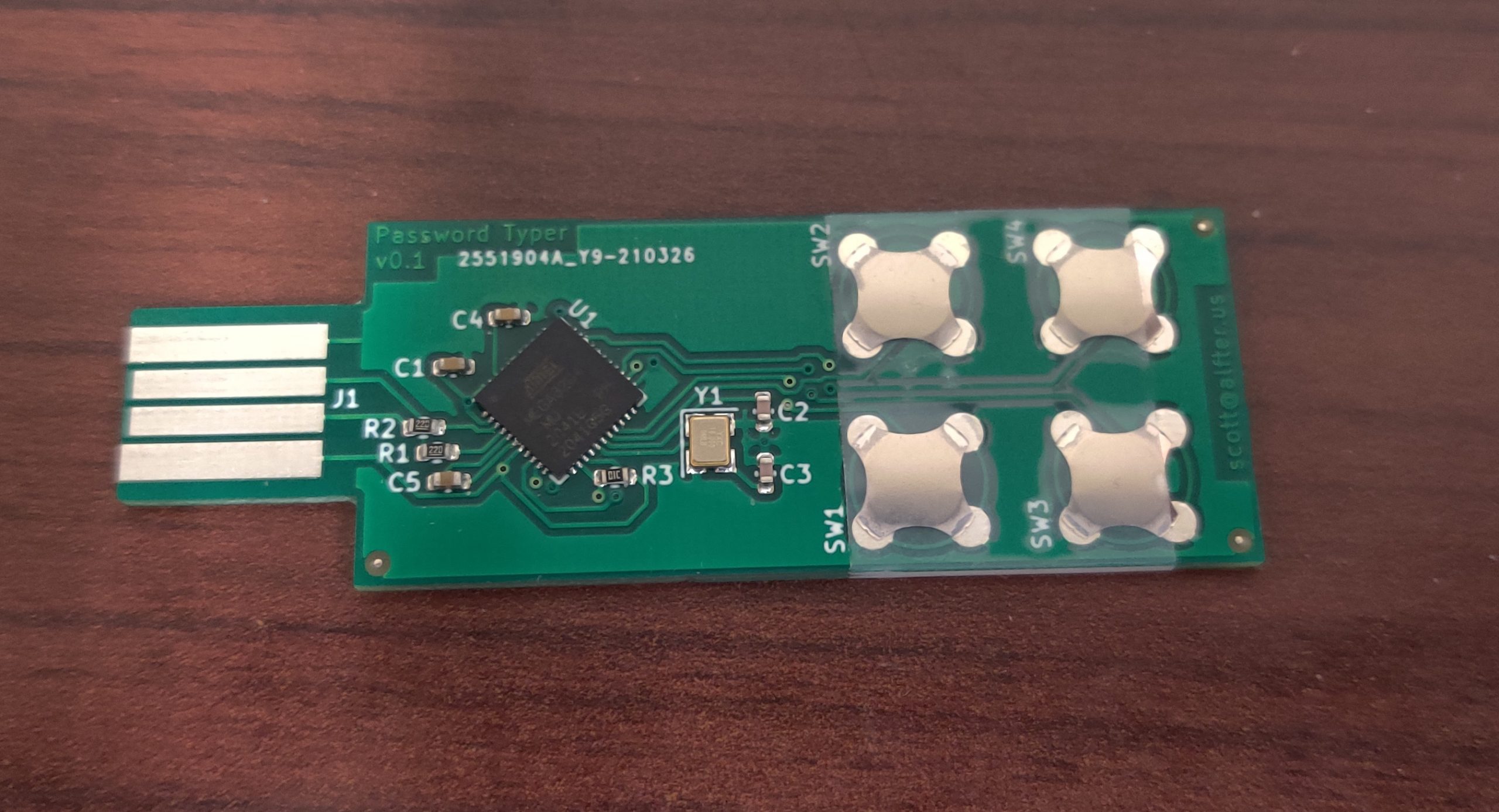
It doesn’t do everything that KeePass does, but it keeps the four passwords you use most on your keychain (or will, once it’s in the 3D-printed case I’ve planned for it). It plugs into a USB port and shows up as a keyboard. It also shows up as a serial interface, through which you can set the text to be sent by each key.
In the past, I’ve ordered boards from companies that make them and stuffed them with parts myself. This time, the boards were handed off to an assembly service that put on everything except the button domes. (They’re not supposed to be soldered; a piece of tape is sufficient to keep them in place.)
Total cost for PCB fabrication and assembly? $52 for 10 pieces of bespoke electronics. The button domes add about another $2 per board, and 3D-printed cases should be about a quarter each.
It’s amazing times we live in that such things are possible. :)
Apparently 800 mA (the default setting in Marlin) was too high a drive current setting for the Y-axis motor in my AM8 (and the extruder motor, too, which was getting hot to the touch). Subsequent experimentation on the X and Z axes suggests that 200 mA should be sufficient for reliable operation without burning things up. I’ve also read that the extra-quiet mode (StealthChop) on the stepper drivers I’m using uses more power than the normal, not-as-quiet (but still not too bad) mode.
Fortunately, I have another printer at the ready to produce a replacement motor mount. It’s already sliced…just need to go home, load purple PETG into the Hypercube, and hit “start.”
A while back, I picked up a cheap Chinese knockoff of a usbASP programmer from Amazon…originally, it was to replace the crummy factory-installed firmware on the Anet A8 motherboard with Marlin. The programmer did its job at the time and was forgotten about for a while. (The A8’s motherboard, meanwhile, crapped the bed after I had only had the printer up and running for maybe a month. It’s long since been rebuilt into an AM8 and the electronics have likewise been through several upgrades, most recently to an SKR 1.4 Turbo with TMC5160 drivers just this past weekend…but that’s getting offtopic.)
I pulled the programmer out again to try configuring some ATMEGA328s for a project. They’re empty chips ordered from DigiKey a while back, and I figured I’d try throwing Optiboot onto them. This should be a simple matter of popping the ATMEGA328 off of an Arduino Uno, plugging in one of the empty chips, plugging the usbASP into the Arduino’s ICSP header, and invoking avrdude with the right options…right?
The programmer wasn’t having any of that. With the preprogrammed chip in the Arduino, avrdude identified the chip, read out the fuses, etc. With an empty chip, it wouldn’t read out the chip ID properly. It said something about not being able to set the clock speed and that an upgrade might fix it.
The homepage for the usbASP had some firmware images, so I grabbed the newest and flashed it according to these instructions. The clock-speed error was gone, but it still wouldn’t work. I tried swapping in other Arduinos and still had no luck.
A bit of poking around led me to this fork of the usbASP firmware, last updated just nine days ago. (By comparison, the “update” I had previously applied was already ten years old!) I burned that to the usbASP, popped an empty chip back into the Arduino Uno, and fired up avrdude. Success! I burned Optiboot, set the fuses, and switched cabling on the Arduino so it was connected with just a USB cable (as usual) instead of the usbASP. The Arduino IDE saw it; I was able to send the “blinky” example to it and get the onboard LED blinking.
I was also able to diddle the fuse settings to change speeds from 16 MHz down to as low as 1 MHz and to run off the internal oscillator instead of an external crystal. I have a stepper-motor tester I started building a while back that was stalled when I think I misprogrammed the fuses and switched it to crystal operation in a circuit with no crystal. Now that the programmer is properly sorted out, I think it’s time to dig up the parts and finish this project.