Monthly Archives: May 2021

Connecting to Bluetooth serial devices on Gentoo LInux

This should’ve been easier, but in hindsight it isn’t too bad. The point-and-drool tools provided for managing Bluetooth (at least under KDE) fall flat on their face, but if you enable some supposedly deprecated options and rebuild BlueZ, you’ll get what you need.

I decided to try getting an HC-05 Bluetooth interface working with one of my 3D printers yesterday. bluedevil (the KDE package that manages Bluetooth) apparently knows nothing about RFCOMM devices (which emulate RS-232 connections over Bluetooth). I had gotten both Android and Windows 10 to talk to my printer over Bluetooth without much fuss: pair the device, fire up a suitable application, and connect.

The needed documentation to get RFCOMM devices working on recent Gentoo builds is a bit sparse, so this post aims to correct that.

First, BlueZ needs to be rebuilt with some more USE flags enabled:

echo net-wireless/bluez deprecated extra-tools readline | sudo tee /etc/portage/package.use/bluez && sudo emerge -1v bluez && sudo /etc/init.d/bluetooth restart

With your HC-05 at least powered up, you can retrieve its MAC address, which is needed for the following step:

hcitool scan

which returns something like this:

Scanning ...
        98:D3:32:10:F7:9C       HC-05

Next, RFCOMM needs to be configured and BlueZ restarted (wherever you see it below, substitute your device’s MAC address for the one used here):

cat <<EOF | sudo tee /etc/bluetooth/rfcomm.conf && sudo /etc/init.d/bluetooth restart
rfcomm {
  bind no;
  device 98:D3:32:10:F7:9C;
  channel 1;
}
EOF

Now we can pair the device to the computer:

sudo rfcomm connect hci0 98:D3:32:10:F7:9C 1

You should be prompted for the HC-05’s PIN; the default is 1234. (Note: while I’ve gotten this working under KDE, I never get prompted for the PIN when in a pure-CLI environment and the connection is refused.) Key it in, and you should get a notice that you’re now connected:

Connected /dev/rfcomm0 to 98:D3:32:10:F7:9C on channel 1
Press CTRL-C for hangup

Press Ctrl-C, then store the PIN for future reference:

for i in /var/lib/bluetooth/[0-9A-F]*; do echo 98:D3:32:10:F7:9C 1234 | sudo tee -a $i/pincodes; done

Create a boot script to bind /dev/rfcomm0:

cat <<EOF | sudo tee /etc/local.d/01-rfcomm-bind.start && sudo chmod +x /etc/local.d/01-rfcomm-bind.start
#!/usr/bin/env bash
rfcomm bind hci0 98:D3:32:10:F7:9C 1
EOF

Run rc-update and verify that both bluetooth and local are both being launched; in my case, both are in the default runlevel. If you reboot now, /dev/rfcomm0 should show up. Use something like minicom to connect, and if your HC-05 is plugged into a printer and the UART interface it’s using is active, you should at least see garbage coming across the line. The HC-05 defaults to 9600 bps, while your printer is probably at 115.2 kbps or faster. The only method I know of to set a different bitrate is to plug it in through an Arduino to bring up the AT-command interface, as described here. It doesn’t seem to support nonstandard speeds like 250 kbps and multiples thereof, and I even had trouble getting 230.4 kbps to work. 115.2 kbps has usually been fast enough to stream gcode without stalling; preprocessing your gcode with something like ArcWelder may help if your printer is running reasonably modern firmware.
PT100 + MAX31865 + SKR 1.4 Turbo + Marlin, revisited

In PT100 + MAX31865 + SKR 1.4 Turbo + Marlin: how to get it all working, I got an RTD sensor working on my printer by sharing its SPI bus connection with the Trinamic motor drivers I’m using. What if you’re using “dumb” drivers like the DRV8825 or A4988, or you’re using some of Trinamic’s other drivers (like the TMC2209) that are configured over a UART connection? This post describes how to use the MicroSD-card SPI connection instead.

One disadvantage is that you can’t use a display that runs on the EXP1/EXP2 headers (such as the ReprapDiscount full-graphic display). (You could, but then you’d need to tap into the SPI bus going to the display’s SD-card slot, which is beyond the scope of this post.) I have one of Bigtreetech’s full-color touchscreens on the way; those plug into a designated connector that uses a UART connection. Until then (and probably after), I have an ESP-01S (running ESP3D) plugged into the 8-pin “WiFi” connector and can control the printer through that. The TFT35 went tango-uniform this past weekend. I pressed the ReprapDiscount display back into service, and it works just fine. I’m still using the MicroSD slot on the SKR instead of the display’s SD slot…not much of a difference.

Hardware Configuration

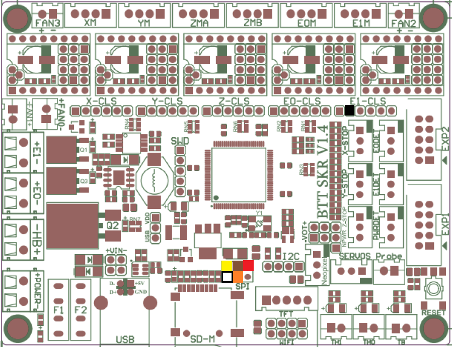
This is largely similar to my previous post, except that you’ll want to make up your cable with female connectors all around. Connections between the MAX31865 board and the SKR Pro 1.4 Turbo are as follows. The SPI connector is near the MicroSD slot; E1-CLS is the closed-loop motor connector for E1 from which we’re drawing 3.3V. The colored boxes overlaid on the board diagram show visually where everything plugs in.

MAX31865 pincolorsignalSKR connection typeSKR connection pin
2whiteGNDfemaleSPI, pin 6
3blackVDDfemaleE1-CLS, pin 2
4brownSCKfemaleSPI, pin 3
5redSDOfemaleSPI, pin 1
6orangeSDIfemaleSPI, pin 4
7yellowCSfemaleSPI, pin 5

Software Configuration

This varies a bit from the software-SPI config. First, the changes to Configuration.h in the thermal-settings section:

#define TEMP_SENSOR_0 -5
#define MAX6675_SS_PIN P0_26
#define MAX31865_SENSOR_OHMS_0 100
#define MAX31865_CALIBRATION_OHMS_0 430
#define MAX31865_USE_60HZ // omit if you're in a 50-Hz part of the world
#define MAX31865_USE_AUTO_MODE
#define MAX31865_USE_READ_ERROR_DETECTION

Make sure SDSUPPORT is enabled:

#define SDSUPPORT

Make sure you’re using the zeleps port of the Adafruit driver, and not the original…the original has lengthy delay loops that will slow your printer considerably. Go into ini/features.ini and look for this line:

TEMP_.+_IS_MAX31865 = Adafruit MAX31865 library@~1.1.0

Change it to this (all on one line):

TEMP_.+_IS_MAX31865 = AdafruitMAX31865Library=https://github.com/zeleps/Adafruit-MAX31865-V1.1.0-Mod-M/archive/master.zip

Next, if you’re using a display plugged into EXP1 and EXP2, you’ll need to disable it. Other features you may have enabled that depend on having a working display may need to be disabled as well. A UART-connected display can be left enabled.

#define REPRAP_DISCOUNT_FULL_GRAPHIC_SMART_CONTROLLER // if it's what you're using

In Configuration_adv.h, make sure the onboard MicroSD slot is selected instead of a display-connected SD slot:

#define SDCARD_CONNECTION ONBOARD

Due to a pullup on the SCK line, we need to use SPI mode 3 instead of mode 0. AFAIK, this doesn’t affect performance; it just changes signaling a little bit. Three changes need to be made to Marlin/src/HAL/LPC1768/HAL_SPI.cpp, which will be presented below as a patch…basically, there are three occurrences of SPI_MODE0 that need to be changed to SPI_MODE3:

diff --git a/Marlin/src/HAL/LPC1768/HAL_SPI.cpp b/Marlin/src/HAL/LPC1768/HAL_SPI.cpp
index 99db15f6e9..ee2bc1fa3d 100644
--- a/Marlin/src/HAL/LPC1768/HAL_SPI.cpp
+++ b/Marlin/src/HAL/LPC1768/HAL_SPI.cpp
@@ -123,7 +123,7 @@
       SPI.setModule(2);
     #endif
     SPI.setDataSize(DATA_SIZE_8BIT);
-    SPI.setDataMode(SPI_MODE0);
+    SPI.setDataMode(SPI_MODE3);
 
     SPI.setClock(SPISettings::spiRate2Clock(spiRate));
     SPI.begin();
@@ -187,7 +187,7 @@ SPIClass::SPIClass(uint8_t device) {
 
   #if BOARD_NR_SPI >= 1
     _settings[0].spi_d = LPC_SSP0;
-    _settings[0].dataMode = SPI_MODE0;
+    _settings[0].dataMode = SPI_MODE3;
     _settings[0].dataSize = DATA_SIZE_8BIT;
     _settings[0].clock = SPI_CLOCK_MAX;
     //_settings[0].clockDivider = determine_baud_rate(_settings[0].spi_d, _settings[0].clock);
@@ -195,7 +195,7 @@ SPIClass::SPIClass(uint8_t device) {
 
   #if BOARD_NR_SPI >= 2
     _settings[1].spi_d = LPC_SSP1;
-    _settings[1].dataMode = SPI_MODE0;
+    _settings[1].dataMode = SPI_MODE3;
     _settings[1].dataSize = DATA_SIZE_8BIT;
     _settings[1].clock = SPI_CLOCK_MAX;
     //_settings[1].clockDivider = determine_baud_rate(_settings[1].spi_d, _settings[1].clock);

If you haven’t previously fixed Adafruit_MAX31865.h (look for it under .pio/libdeps/LPC1769/), find this line near the top: Skip this step, as the zeleps driver includes this fix already:

#if (ARDUINO >= 100)

and change ARDUINO to ARDUINOLPC:

#if (ARDUINOLPC >= 100)

Notes

At first, I had noticed a bit of lag in the printer with the temperature sensor using a soft-SPI connection and thought I’d try switching to a hardware SPI port to see if it’ll lighten the load a bit. It didn’t. It was mainly noticeable in the display and when homing the printer. It didn’t seem to affect print speed or quality when printing from local storage, but streaming a print from something like OctoPrint or Pronterface stumbled pretty badly. What finally fixed this issue was the updated MAX31865 driver.

If you want to use the SD-card slot on the ReprapDiscount display, you might try using the SPI bus on the EXP2 connector instead. This might require driving the MAX31865 board with 5V instead of 3.3V to match the display’s 5V interface. The easiest way to tap into the signals would likely be a 2×5 female insulation-displacement connector on the EXP2 ribbon cable, into which pins can be stuck in the appropriate places. Set SDCARD_CONNECTION to LCD instead of ONBOARD if you go this route.