Whatever you do, don’t paste the code block above into OpenSCAD and render it into an STL. Whatever you do, do not load that STL into a slicer. Whatever you do, don’t send that sliced STL to your 3D printer. Above all else, don’t pull the resulting object off of your printer and drop it into an AR-pattern modern sporting rifle.
This should’ve been easier, but in hindsight it isn’t too bad. The point-and-drool tools provided for managing Bluetooth (at least under KDE) fall flat on their face, but if you enable some supposedly deprecated options and rebuild BlueZ, you’ll get what you need.
I decided to try getting an HC-05 Bluetooth interface working with one of my 3D printers yesterday. bluedevil (the KDE package that manages Bluetooth) apparently knows nothing about RFCOMM devices (which emulate RS-232 connections over Bluetooth). I had gotten both Android and Windows 10 to talk to my printer over Bluetooth without much fuss: pair the device, fire up a suitable application, and connect.
The needed documentation to get RFCOMM devices working on recent Gentoo builds is a bit sparse, so this post aims to correct that.
First, BlueZ needs to be rebuilt with some more USE flags enabled:
You should be prompted for the HC-05’s PIN; the default is 1234. (Note: while I’ve gotten this working under KDE, I never get prompted for the PIN when in a pure-CLI environment and the connection is refused.) Key it in, and you should get a notice that you’re now connected:
Connected /dev/rfcomm0 to 98:D3:32:10:F7:9C on channel 1
Press CTRL-C for hangup
Press Ctrl-C, then store the PIN for future reference:
for i in /var/lib/bluetooth/[0-9A-F]*; do echo 98:D3:32:10:F7:9C 1234 | sudo tee -a $i/pincodes; done
Run rc-update and verify that both bluetooth and local are both being launched; in my case, both are in the default runlevel. If you reboot now, /dev/rfcomm0 should show up. Use something like minicom to connect, and if your HC-05 is plugged into a printer and the UART interface it’s using is active, you should at least see garbage coming across the line. The HC-05 defaults to 9600 bps, while your printer is probably at 115.2 kbps or faster. The only method I know of to set a different bitrate is to plug it in through an Arduino to bring up the AT-command interface, as described here. It doesn’t seem to support nonstandard speeds like 250 kbps and multiples thereof, and I even had trouble getting 230.4 kbps to work. 115.2 kbps has usually been fast enough to stream gcode without stalling; preprocessing your gcode with something like ArcWelder may help if your printer is running reasonably modern firmware.
In PT100 + MAX31865 + SKR 1.4 Turbo + Marlin: how to get it all working, I got an RTD sensor working on my printer by sharing its SPI bus connection with the Trinamic motor drivers I’m using. What if you’re using “dumb” drivers like the DRV8825 or A4988, or you’re using some of Trinamic’s other drivers (like the TMC2209) that are configured over a UART connection? This post describes how to use the MicroSD-card SPI connection instead.
One disadvantage is that you can’t use a display that runs on the EXP1/EXP2 headers (such as the ReprapDiscount full-graphic display). (You could, but then you’d need to tap into the SPI bus going to the display’s SD-card slot, which is beyond the scope of this post.) I have one of Bigtreetech’s full-color touchscreens on the way; those plug into a designated connector that uses a UART connection. Until then (and probably after), I have an ESP-01S (running ESP3D) plugged into the 8-pin “WiFi” connector and can control the printer through that. The TFT35 went tango-uniform this past weekend. I pressed the ReprapDiscount display back into service, and it works just fine. I’m still using the MicroSD slot on the SKR instead of the display’s SD slot…not much of a difference.
Hardware Configuration
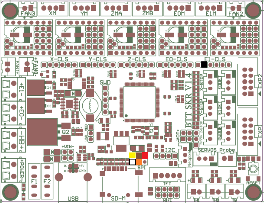
This is largely similar to my previous post, except that you’ll want to make up your cable with female connectors all around. Connections between the MAX31865 board and the SKR Pro 1.4 Turbo are as follows. The SPI connector is near the MicroSD slot; E1-CLS is the closed-loop motor connector for E1 from which we’re drawing 3.3V. The colored boxes overlaid on the board diagram show visually where everything plugs in.
MAX31865 pin
color
signal
SKR connection type
SKR connection pin
2
white
GND
female
SPI, pin 6
3
black
VDD
female
E1-CLS, pin 2
4
brown
SCK
female
SPI, pin 3
5
red
SDO
female
SPI, pin 1
6
orange
SDI
female
SPI, pin 4
7
yellow
CS
female
SPI, pin 5
Software Configuration
This varies a bit from the software-SPI config. First, the changes to Configuration.h in the thermal-settings section:
#define TEMP_SENSOR_0 -5
#define MAX6675_SS_PIN P0_26
#define MAX31865_SENSOR_OHMS_0 100
#define MAX31865_CALIBRATION_OHMS_0 430
#define MAX31865_USE_60HZ // omit if you're in a 50-Hz part of the world
#define MAX31865_USE_AUTO_MODE
#define MAX31865_USE_READ_ERROR_DETECTION
Make sure SDSUPPORT is enabled:
#define SDSUPPORT
Make sure you’re using the zeleps port of the Adafruit driver, and not the original…the original has lengthy delay loops that will slow your printer considerably. Go into ini/features.ini and look for this line:
Next, if you’re using a display plugged into EXP1 and EXP2, you’ll need to disable it. Other features you may have enabled that depend on having a working display may need to be disabled as well. A UART-connected display can be left enabled.
#define REPRAP_DISCOUNT_FULL_GRAPHIC_SMART_CONTROLLER // if it's what you're using
In Configuration_adv.h, make sure the onboard MicroSD slot is selected instead of a display-connected SD slot:
#define SDCARD_CONNECTION ONBOARD
Due to a pullup on the SCK line, we need to use SPI mode 3 instead of mode 0. AFAIK, this doesn’t affect performance; it just changes signaling a little bit. Three changes need to be made to Marlin/src/HAL/LPC1768/HAL_SPI.cpp, which will be presented below as a patch…basically, there are three occurrences of SPI_MODE0 that need to be changed to SPI_MODE3:
If you haven’t previously fixed Adafruit_MAX31865.h (look for it under .pio/libdeps/LPC1769/), find this line near the top: Skip this step, as the zeleps driver includes this fix already:
#if (ARDUINO >= 100)
and change ARDUINO to ARDUINOLPC:
#if (ARDUINOLPC >= 100)
Notes
At first, I had noticed a bit of lag in the printer with the temperature sensor using a soft-SPI connection and thought I’d try switching to a hardware SPI port to see if it’ll lighten the load a bit. It didn’t. It was mainly noticeable in the display and when homing the printer. It didn’t seem to affect print speed or quality when printing from local storage, but streaming a print from something like OctoPrint or Pronterface stumbled pretty badly. What finally fixed this issue was the updated MAX31865 driver.
If you want to use the SD-card slot on the ReprapDiscount display, you might try using the SPI bus on the EXP2 connector instead. This might require driving the MAX31865 board with 5V instead of 3.3V to match the display’s 5V interface. The easiest way to tap into the signals would likely be a 2×5 female insulation-displacement connector on the EXP2 ribbon cable, into which pins can be stuck in the appropriate places. Set SDCARD_CONNECTION to LCD instead of ONBOARD if you go this route.
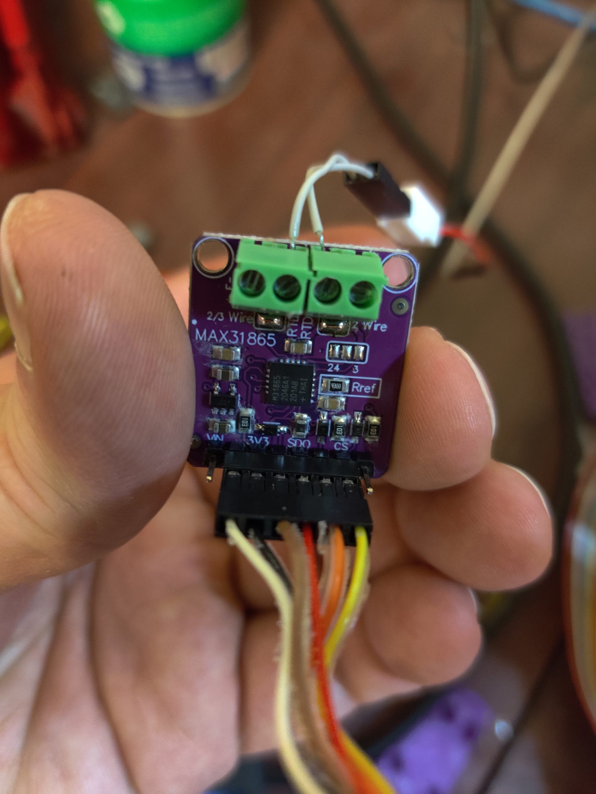
I wanted to upgrade one of my 3D printers to make it capable of printing with high-temperature materials. One of the things needed to pull that off is to replace the usual hotend thermistor (which maxes out around 280°C) with either a thermocouple (which can go into the thousands of degrees) or a platinum RTD (which, as packaged for printers, can usually go to 500° or so). Either of these requires additional electronics to make the device compatible; for a PT100 RTD, the device in question is a little board with a MAX31865 on it, which converts the small change in resistance of the RTD to a digital readout over SPI.
There is a guide to getting all this stuff working, but it seems unnecessarily involved while not providing all of your options. What follows is a simpler explanation that will get you up and running.
(I assume that you’re running the bugfix-2.0.x branch of Marlin, and that your printer has a single hotend with a thermistor that you want to replace with an RTD. For my upgrade, I also replaced the aluminum heater block with a nickel-plated copper block. I also have a 60W heater on order, as the 40W heater I’ve been using is having a hard time maintaining temperature with the blower running. Further, I assume that you’re using Trinamic 2130 or 5160 drivers and that you’re using SPI to configure them…we’re going to share that SPI connection. We’ll tap into most of the SPI signals at the E1 connector. If you have a second extruder, you might want to build something like this adapter.)
Hardware Configuration
When the parts arrive, you’ll most likely need to solder connectors onto the MAX31865 board. They should be in the bag with the board; assembly is self-explanatory. There are also a couple of jumper pads that need to be soldered together to put the chip in 2-pin mode.
You’ll also want to make a cable to connect to the SKR 1.4 Turbo. It should have a six-pin female Dupont connector on the MAX31865 end. The SKR end should have six one-pin Dupont connectors: one female (for the CS signal, along one edge of the cable if you’re using ribbon cable) and the rest male. Let’s say you’re using the same color coding that I used, based on the cables I had laying around:
MAX31865 pin
color
signal
SKR connection type
SKR connection pin
2
white
GND
male
E1, pin 8
3
black
VDD
male
E1, pin 9
4
brown
SCK
male
E1, pin 3
5
red
SDO
male
E1, pin 5
6
orange
SDI
male
E1, pin 2
7
yellow
CS
female
PWRDET, pin 3
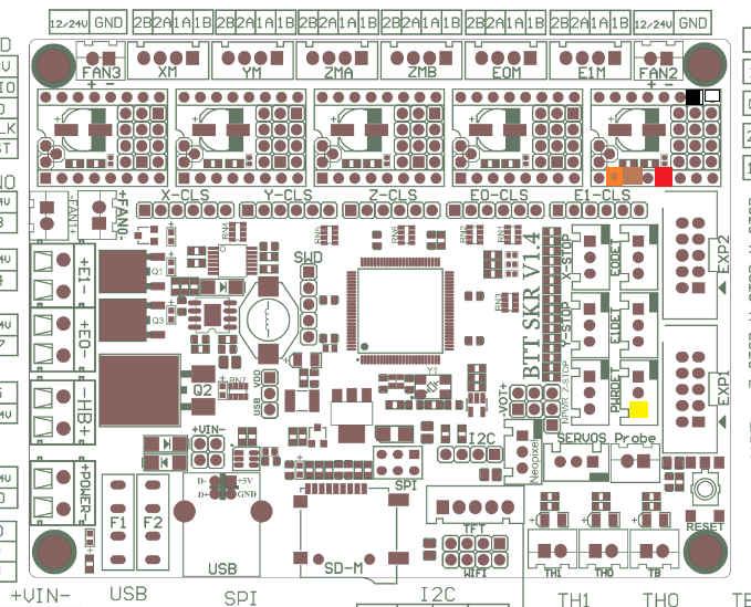
Pins 1 (5V) and 8 (RDY) on the MAX31865 aren’t used, as it and the printer motherboard are both 3.3V devices. A color-coded map of connections to the SKR 1.4 Turbo follows:
The RTD should be connected to the middle two terminals on the side opposite the SPI connector. Mine came with a 2-pin Molex connector, so I just knocked together a little adapter with a Dupont connector and some wire. Take note that the 6-pin connector is centered on the board’s 8-pin connector.
Software Configuration
With the hardware sorted, we now turn to configuring Marlin. Most of the changes can go in the thermal-settings section of Configuration.h.
#define TEMP_SENSOR_0 -5
#define MAX31865_MOSI_PIN TMC_SW_MOSI
#define MAX31865_MISO_PIN TMC_SW_MISO
#define MAX31865_SCK_PIN TMC_SW_SCK
#define MAX6675_SS_PIN POWER_LOSS_PIN // MAX31865_CS_PIN is copied from this
#define MAX31865_SENSOR_OHMS_0 100
#define MAX31865_CALIBRATION_OHMS_0 430
#define MAX31865_USE_60HZ // omit this if you're in a 50-Hz part of the world
#define MAX31865_USE_AUTO_MODE
#define MAX31865_USE_READ_ERROR_DETECTION
Trinamic drivers on the SKR 1.4 Turbo use software SPI, so that’s what we end up selecting here. MOSI (SDI), MISO (SDO), and SCK pins are set to the same ones the Trinamic drivers use, while the CS pin is set to a pin that we’re not using so we can still install a second extruder in the future. Any pin that doesn’t have a pullup or pulldown is OK…I’m using the pin on the PWRDET connector.
To use hardware SPI, the MAX31865_*_PIN entries don’t need to be defined. Just define MAX6675_SS_PIN, which is copied internally to MAX31865_CS_PIN. From what I’ve read, if there are multiple hardware SPI buses, the driver will default to using one of them and there’s no way to choose the other. I haven’t had a chance to verify this behavior.
If you’re using a PT1000 instead of a PT100, the MAX31865_*_OHMS values both need to be multiplied by 10 and you need to replace the Rref resistor on the MAX31865 board with a 4.3kΩ part (stock is a 430Ω 0.1% 0805 SMD resistor).
There’s also a change needed in Adafruit_MAX31865.h (in my source tree, it’s in .pio/libdeps/LPC1769/Adafruit MAX31865 library). Line 49 (or thereabouts) looks like this:
#if (ARDUINO >= 100)
ARDUINO isn’t defined by the LPC176x Arduino framework; instead, it needs to look at ARDUINOLPC:
#if (ARDUINOLPC >= 100)
Without this change, you’ll get compile errors saying that WProgram.h can’t be found.
Instead of the above, there’s an updated driver for the MAX31865 that also fixes some serious performance issues with the original. Go into ini/features.ini and look for this line:
With these changes made, compile, write the firmware.bin file that’s produced to a MicroSD card, pop it into the slot on the SKR, and hit Reset (or power it up).
Other Notes
I’ve noticed that the Marlin UI (on one of the cheap 128×64 graphical LCDs) is a bit laggy, but the printer is otherwise running properly. Switching from the software SPI used for Trinamic drivers to one of the hardware SPI channels might fix that. If I’m not mistaken, there are two: one is brought out on the EXP2 connector for cheap 128×64 graphical LCDs like mine (to go to the SD-card slot on such devices), and another goes to the onboard MicroSD slot and is also available on an SPI header adjacent to that slot. Changing MAX31865_MOSI_PIN, MAX31865_MISO_PIN, and MAX31865_SCK_PIN to use those other channels ought to do the trick (and leave out MAX31865_USES_SW_SPI if you do that).
Display lag and other issues were the result of lengthy delays hardcoded in the Adafruit driver. The zeleps fork of that driver appears so far to have fixed that problem. I currently have the MAX31865 board sharing hardware SPI with the onboard MicroSD slot, but sharing it with the display or with Trinamic drivers should work as well, whether with hardware or software SPI.
I’ve also given some thought to trying ReprapFirmware, now that you don’t need to fork over the big bucks for a Duet to run it. How this setup would cooperate with that, I don’t know.
Apparently 800 mA (the default setting in Marlin) was too high a drive current setting for the Y-axis motor in my AM8 (and the extruder motor, too, which was getting hot to the touch). Subsequent experimentation on the X and Z axes suggests that 200 mA should be sufficient for reliable operation without burning things up. I’ve also read that the extra-quiet mode (StealthChop) on the stepper drivers I’m using uses more power than the normal, not-as-quiet (but still not too bad) mode.
Fortunately, I have another printer at the ready to produce a replacement motor mount. It’s already sliced…just need to go home, load purple PETG into the Hypercube, and hit “start.”
Doing some electronics testing now…have the Arduino Due, RAMPS-FD v2.2 (the one I built a while back), a 128×64 LCD module (the usual ReprapDiscount design), and a Raspberry Pi 3 B+ all hooked together, with OctoPrint running on 64-bit Gentoo on the Raspberry Pi.
Some issues:
At some point, something changed in Marlin such that it now doesn’t want to write to the EEPROM. M500 throws an error: “field esteppers mismatch” [sic].
The SD-card slot in the display works well enough to get a listing, but not to read or write files, which makes it kinda useless. I reworked the display adapter a little to use a different chip (a 74HCT244 instead of a 74HC07) that was more readily available, but could this substitution affect SD-card performance? Should I try whacking in a 74HC244, or should I go back to the original design and hope I can find 74HC07s somewhere?
On the other hand, I did get OctoPrint to talk to the Due/RAMPS stack over the Due’s native USB port, which is much faster than the “programming” port that uses the same ATMEGA16U2 as in the 8-bit Arduinos. (Marlin images are burned through the native port in about 4 seconds, vs. 32 seconds when going through the AVR.) I had to patch OctoPrint’s firmware updater plugin to talk to the native port; those changes have been put in a pull request. Maybe faster communication between the Raspberry Pi and the Arduino Due’s native USB port will mitigate the need for the SD-card slot when running complex print jobs.
Just got the CoreXY mechanism working. This is just the right motor, but I also checked the left motor and it moved the carriage the other way. I think I’ll need to put endstops on the rods to constrain motion so that (for instance) the hotend doesn’t slam into the motors; that should be a fairly simple design. (I’m thinking printed rings clamped to the rods with screws, as I plan on using stall detection in the TMC2130 drivers in place of endstop switches on X and Y.)
Right now, I’m driving one motor at a time with a DRV8825 stepstick and a Teensy 2.0 on a breadboard. Maybe it’s time to finish wiring the electronics. :)
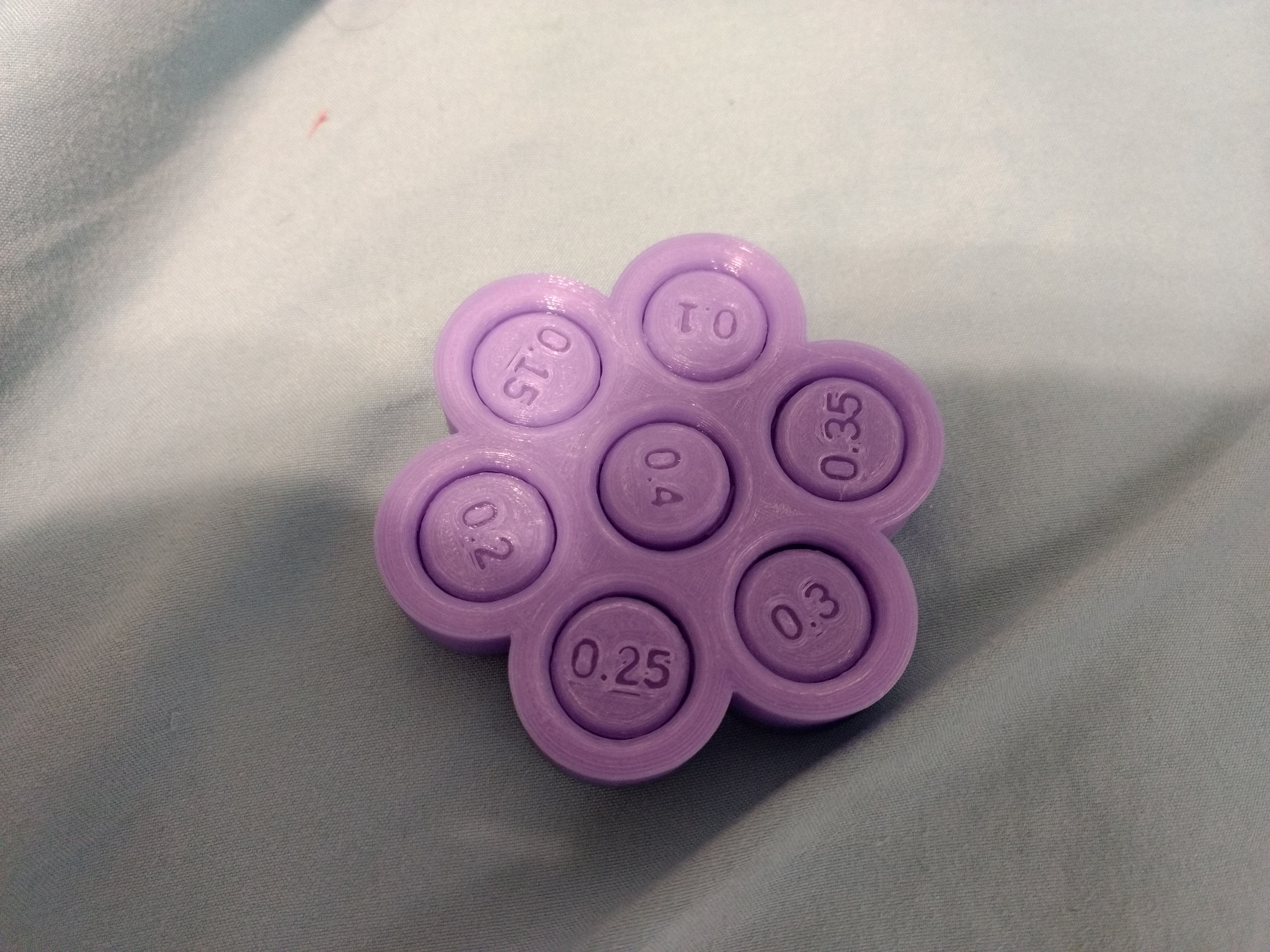
For the first time, I printed this tolerance test and got all of the inserts to spin. 0.1 mm took a little bit of persuasion, but I was able to break it loose with my fingers. Previously, I was lucky if I could break 0.2 mm loose at all, and I’d frequently need tools to break gaps smaller than 0.3 mm loose.
What changed? I’m calculating flow percentages for my filament, according to this page I ran across recently:
I also usually set the first-layer horizontal expansion to something like -0.1 mm to combat elephant foot. That and overextrusion from the default 100% flow rate (I’d sometimes punch in 95% for PLA if I remembered, but the rolls I’ve tested so far have come back at 90-92%) were the likely culprits of previous tolerance tests that got stuck.
Bottom line: high precision (by 3D-printer standards, anyway) is achievable, even with the A8. :)
A few months back, I bought my first 3D printer, an Anet A8 kit for somewhere around $150, shipped. It was an OK printer to start with, but various upgrades (and a repair or two) have made it into a fairly solid workhorse that still hasn’t come home from the office.
I replaced the stock firmware (whatever it was) with Marlin fairly early on. When the original motherboard crapped out after a month or two, I replaced it with an Arduino Mega and RAMPS 1.4 combination with DRV8825 stepper drivers, which made the printer both quieter and more precise.
I’m now building a Hypercube 300 for use at home. While looking into hardware and software options for that, I ran across Klipper, a relative newcomer with a different idea: move most of the computations for 3D printing out of the weedy little 16-MHz 8-bit AVR microcontroller on an Arduino and onto the much faster 1.4-GHz quad-core 64-bit ARM microprocessor in a Raspberry Pi 3. (Raspbian only has a 32-bit userspace, but I’ve built Gentoo with a 64-bit userspace…but that’s straying off-topic.) The Arduino is retained, but only as a real-time auxiliary controller that only makes sure the commands sent to it by the Raspberry Pi are carried out on time and in the right order.
I thought I’d seen some video of a Klipper-powered Hypercube a while back…can’t find it now, but here’s a Creality CR10 running at 100 mm/s with Klipper. My A8’s been loafing along at 60. I need to look into this.
Since I already had a Raspberry Pi running OctoPrint plugged into the A8, I thought I’d give Klipper a shot. It took a while to get the configuration sorted out (it’s here), but this morning I got it pretty much stabilized. First print was a Cali Dog, and it turned out just fine at 60 mm/s. With basic functionality sorted, I figured I’d try seeing how fast my printer could go.
I sliced it in Cura 3.4.1 with some basic settings: 60 mm/s base speed, 2 perimeters all around, 15% cubic infill, and a 350-mm skirt to get the nozzle primed. I also used a set of ChangeAtZ post-processing scripts to increase the feedrate every 8 mm, from 100% at the bottom to 200% at the top. This produces 8-mm sections printed at 60, 72, 84, 96, and 108 mm/s, capped by a 10-mm section printed at 120 mm/s. That’s the theory, at least.
I used Dazzle Light red PLA for all prints, laid down with a 210°C hotend onto a 55°C bed.
Since Klipper was already on the printer, I let it go first:
You can hear it get faster on each programmed feedrate change, and the finished quality is pretty good. There’s what looks like a seam on one side where I think it always started the outer wall, but that’s it. Print time was 20 minutes.
Next up, I flashed Marlin back onto the printer. I only tweaked the gcode for different homing and bed-leveling commands used by Klipper and Marlin; the rest was unaltered. Here’s what I got with Marlin:
Even at 60 mm/s, the printer was stuttering on the inner perimeter. Each “circle” is cut into 90 short line segments, and the resultant flood of gcode couldn’t be sent fast enough. At 72 mm/s, it got even worse. Now, the printer was stuttering on the (visible) outer perimeter as well, which produced stippling artifacts where the printhead stopped and restarted. It never got any faster; if it was having trouble keeping up at slower speeds, it certainly wasn’t going to do any better with faster speeds. To add insult to injury, print time increased to 33 minutes. Slower and worse quality.
I’d heard somewhere that sometimes the USB serial connection from OctoPrint to Marlin can be a bottleneck, so I put the gcode on an SD card and printed it again:
Not much faster than when printing from OctoPrint (finished in about 30 minutes), but at least the quality was much better. It wasn’t too different from what Klipper produced, other than that it took about 50% longer.
Here’s a close-up of the three prints side-by-side:
(K=Klipper, M=Marlin streamed from OctoPrint, MS=Marlin printed from SD card)
Even without zooming in, the stippling is quite visible on the middle cylinder.
Bottom line: Klipper’s a little bit more tricky to install, and it’s not yet as loaded with features as Marlin (Klipper currently does nothing with the rotary encoder or kill button on the display, and it doesn’t have automated filament changing), but the speed and quality improvements make it a winner for most daily use. If I need something that only Marlin handles for now, it’s easy enough to switch back to it temporarily.