Plated through-holes have long been one of the things you could get from the likes of OSH Park or JLCPCB that were difficult to impossible to produce at home. This morning, I stumbled across this video from four years ago:
This method uses chemicals that should be relatively easy to source and a bench power supply for constant-current plating. He uses a CNC mill to mill and drill the board and a 3D-printed frame to support the PCB and copper plates, but I could’ve done this back in the day with etched photo-resist boards and a drill press.
I lost my first Tindie sale to misplaced email. By the time I discovered I’d had an order come in, it had already been refunded automatically. Determined to avoid a repeat, I figured that a display of some sort that could be updated with live order information from Tindie, H3 Hab Bazaar, and elsewhere would be useful for making sure orders are handled expeditiously.
For display elements, I wanted LED modules that aren’t too ridiculously large, and a single color would be sufficient. Adafruit has charlieplexed 16×9 LED matrix boards (such as this) that are just a mess of 0603 LEDs wired together appropriately. They’re meant to be used with this driver board, which provides an I2C interface. As many as four boards can be used together on one I2C bus; that’ll make a 64×9 display about eight inches wide and an inch tall. I2C allows use of something small and cheap like an ESP-01 module that also provides WiFi so the display can be reconfigured on the fly.
Here’s the prototype, with two of the display modules connected:
(It looks brighter in person than it does in the video. That said, I also have the brightness dialed way back from maximum. You can crank it bright enough that your eyes will bleed. :-) The blue LED on the ESP-01 is connected to GPIO2, which we’re using for the I2C clock…that’s why it’s lit up.)
It’s just a fixed string right now, with WiFi disabled. Adding the rest of the displays is a matter of soldering them together and daisy-chaining them with some cables. I intend to put the displays in a 3D-printed enclosure and hang it on the wall, with some code running on my home server to update the display periodically over WiFi.
Finding code that uses multiple Adafruit_GFX-compatible displays and treats them as one unit was a bit tricky. I thought it might combine the four 16×9 screens into a single 64×9 virtual screen, but it doesn’t. Instead, your code needs to divide the image across the four screens. Fortunately, Adafruit_GFX allows for graphics coordinates outside the range of the screen, which (1) facilitates smooth scrolling by allowing the same text to be written one pixel to the left at a time and (2) allows the same content to be written to multiple screens with different offsets so they end up showing a larger image. Here’s the code that runs the demo in the video shown above:
#include <Arduino.h>
#include <Wire.h>
#include <Adafruit_GFX.h>
#include <Adafruit_IS31FL3731.h>

#define NUM_SCREENS 2
#define BRIGHTNESS 8

Adafruit_IS31FL3731 matrix0 = Adafruit_IS31FL3731();
#if NUM_SCREENS>=2
Adafruit_IS31FL3731 matrix1 = Adafruit_IS31FL3731();
#endif
#if NUM_SCREENS>=3
Adafruit_IS31FL3731 matrix2 = Adafruit_IS31FL3731();
#endif
#if NUM_SCREENS>=4
Adafruit_IS31FL3731 matrix3 = Adafruit_IS31FL3731();
#endif

void setup() {
  // set up I2C
  Wire.pins(0,2); // SDA on GPIO0, SCL on GPIO2
  Wire.begin(0,2);

  // connect to display(s)
  if (! matrix0.begin(0x74))
    while (1);
  #if NUM_SCREENS>=2
  if (! matrix1.begin(0x75))
    while (1);
  #endif
  #if NUM_SCREENS>=3
  if (! matrix2.begin(0x76))
    while (1);
  #endif
  #if NUM_SCREENS>=4
  if (! matrix3.begin(0x77))
    while (1);
  #endif
}

void loop() {

  String msg="The quick brown fox jumps over the lazy dog.";

  msg="    "+msg+"    ";
  matrix0.setRotation(0);
  matrix0.setTextSize(1);
  matrix0.setTextWrap(false);
  matrix0.setTextColor(BRIGHTNESS,0);
  matrix0.clear();
  #if NUM_SCREENS>=2
  msg="    "+msg+"    ";
  matrix1.setRotation(0);
  matrix1.setTextSize(1);
  matrix1.setTextWrap(false);
  matrix1.setTextColor(BRIGHTNESS,0);
  matrix1.clear();
  #endif
  #if NUM_SCREENS>=3
  msg="    "+msg+"    ";
  matrix2.setRotation(0);
  matrix2.setTextSize(1);
  matrix2.setTextWrap(false);
  matrix2.setTextColor(BRIGHTNESS,0);
  matrix2.clear();
  #endif
  #if NUM_SCREENS>=4
  msg="    "+msg+"    ";
  matrix3.setRotation(0);
  matrix3.setTextSize(1);
  matrix3.setTextWrap(false);
  matrix3.setTextColor(BRIGHTNESS,0);
  matrix3.clear();
  #endif

  for (int i=0; i<msg.length()-4*NUM_SCREENS; i++)
  {
    String segment=msg.substring(i, i+4*NUM_SCREENS);
    for (int8_t x=0; x>-6; x--) {
      matrix0.setCursor(x,0);
      matrix0.print(segment);
      #if NUM_SCREENS>=2
      matrix1.setCursor(x-16,0);
      matrix1.print(segment);
      #endif
      #if NUM_SCREENS>=3
      matrix2.setCursor(x-32,0);
      matrix2.print(segment);
      #endif
      #if NUM_SCREENS>=4
      matrix3.setCursor(x-48,0);
      matrix3.print(segment);
      #endif
      delay(25);
    }
  }
}
I really wanted an array of Adafruit_IS31FL3731 instances that I could iterate through with loops, but I couldn’t get that to work, so instead the loops are unrolled with a bunch of #ifdefs to control how many are produced, based on the number of attached screens. At first I was running with one screen, but last night I got it running with two. I haven’t yet tested it, but three or four screens should work as well.
This code builds in PlatformIO, and I currently have it targeting the ESP-01 (which uses an ESP8266). Before I figured out how to enable I2C on the ESP-01, I had a single screen driven by an Arduino Nano, but I’ve seen posts elsewhere indicating that it might not have enough RAM to handle multiple screens.
Next task is to set up some sort of control interface (probably web-based) to allow content to be changed on the fly, and to knock together an enclosure so it’s more than just a bunch of boards and wires.
The standard instructions for getting the Raspberry Pi Pico SDK up and running mostly work on Gentoo Linux, but there are a few exceptions (especially with regard to setting up the needed ARM cross-compiler). This is a summary of what I figured out over the course of a couple of hours on a Sunday morning, adding the needed components to my system to get the provided “blinky” example to compile without errors. (I don’t yet have a Raspberry Pi Pico to test with, but they’re on order from Sparkfun and will probably arrive sometime this week.)
Install the ARM Cross-Compiler
This is the biggest divergence from the published directions. Gentoo has a system called crossdev that makes building cross-compilers ridiculously easy. If you don’t already have it enabled (I already had AVR, ARM, and RISC-V cross-compilers for other purposes, though the ARM compilers I already had were for cross-compiling for Gentoo on Raspberry Pi SBCs, not the Raspberry Pi Pico), go get it. Even if you’re running Gentoo Linux on a Raspberry Pi SBC, you’ll need this for the Pico:
sudo emerge crossdev
Then, to build the necessary cross-compiler, do this…-s4 ensures that we get a C++ compiler as well as a C compiler:
sudo crossdev -s4 --target arm-none-eabi
Install the Raspberry Pi Pico SDK
This pretty much goes by the book. You’ll need Git installed…if you haven’t done that already, go take care of that. Then, get the SDK:
Log out and back in before continuing to make sure the new variables are in your environment.
Install VSCodium
VSCodium is the fully-open-source version of Visual Studio Code. Mainly it lacks the telemetry code that phones home to Microsoft with your usage. There is of course an ebuild in Portage, but before we install it, there’s a fix I like to apply that helps with plugin availability (in particular, it gets PlatformIO up and running in VSCodium). The following will do both:
There are a couple of extensions you’ll want to grab to better integrate Pico SDK projects into VSCodium:
C/C++ IntelliSense
CMake
CMake Tools
Cortex-Debug
Try It Out
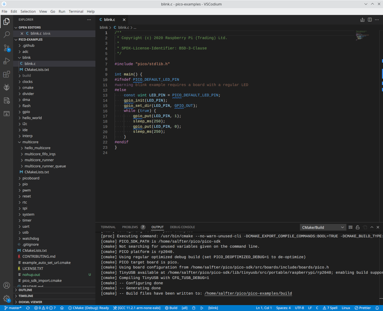
Start VSCodium from a shell prompt (the needed environment variables may or may not show up if you launch it from some desktop facility). We’ll start with the provided examples:
nohup vscodium ~/pico/pico-examples &
If everything’s set up right, you’ll get some messages from cmake in the output window and a few options to select at the bottom of the window:
Where it says “CMake: [Debug]: Ready,” you can click to choose between different build options: debug, release, etc. To the right of that, you pick the compiler to use…whatever the exact version is, it should have “arm-none-eabi” as part of the name. To the right of that is the “Build” button, and right next to build, you can click where it says “[all]” to pick one of the examples to build. Click on it, select “blink”, then click “Build.” After a short time (maybe a second on the Ryzen 7 3800X I’m running), the output window should say the build is complete with no errors. ~/pico/pico-examples/build/blink/blink.uf2 is the file that you’d then transfer into a Raspberry Pi Pico for execution.
The vertical lines in the screen, while present, aren’t as obvious as they are in the photo. The time is off because it’s not on my home network right now and can’t retrieve the correct time.
I’ve been playing around a bit with ESPHome and Home Assistant lately…started with a couple of Sonoff smart outlets, one to replace a Kill-A-Watt monitoring my mining rig and another to switch a light on at sunset.
What’s up above is part of this weather station kit. The metal can on the small board in the center is a BME280 environmental sensor that picks up temperature, humidity, and barometric pressure and makes that information available over I2C. The NodeMCU on the right reads the sensor, publishes its readings over WiFi to a Home Assistant server, and displays the readings (and current time) on the I2C-connected OLED on the left. You could probably use an ESP-01S with a 4-MB flash upgrade since I2C only needs two pins to work, but the kit came with a NodeMCU, so that’s how I brought it up initially.
Wiring is simple: connect ground together on all three boards, connect the power inputs on the OLED and sensor to a 3.3V pin on the NodeMCU, connect the data pins (SDA) to pin D2, and connect the clock pins (SCK) to pin D1.
The ESPHome config file (not really a program as such) looks something like this:
The sensor returns temperature in °C and barometric pressure in hPa; the code above converts those to more sensible units for display. Also, you’ll probably need to update the font file location to whatever is correct for your system. (I have ESPHome installed on Gentoo Linux and have the corefonts package installed.)
Something like this would be useful to have indoors. For an outdoors weather sensor, leave off the screen and the related sections (display, time, and font) from the config file. Next task is to fab up an enclosure of some sort.
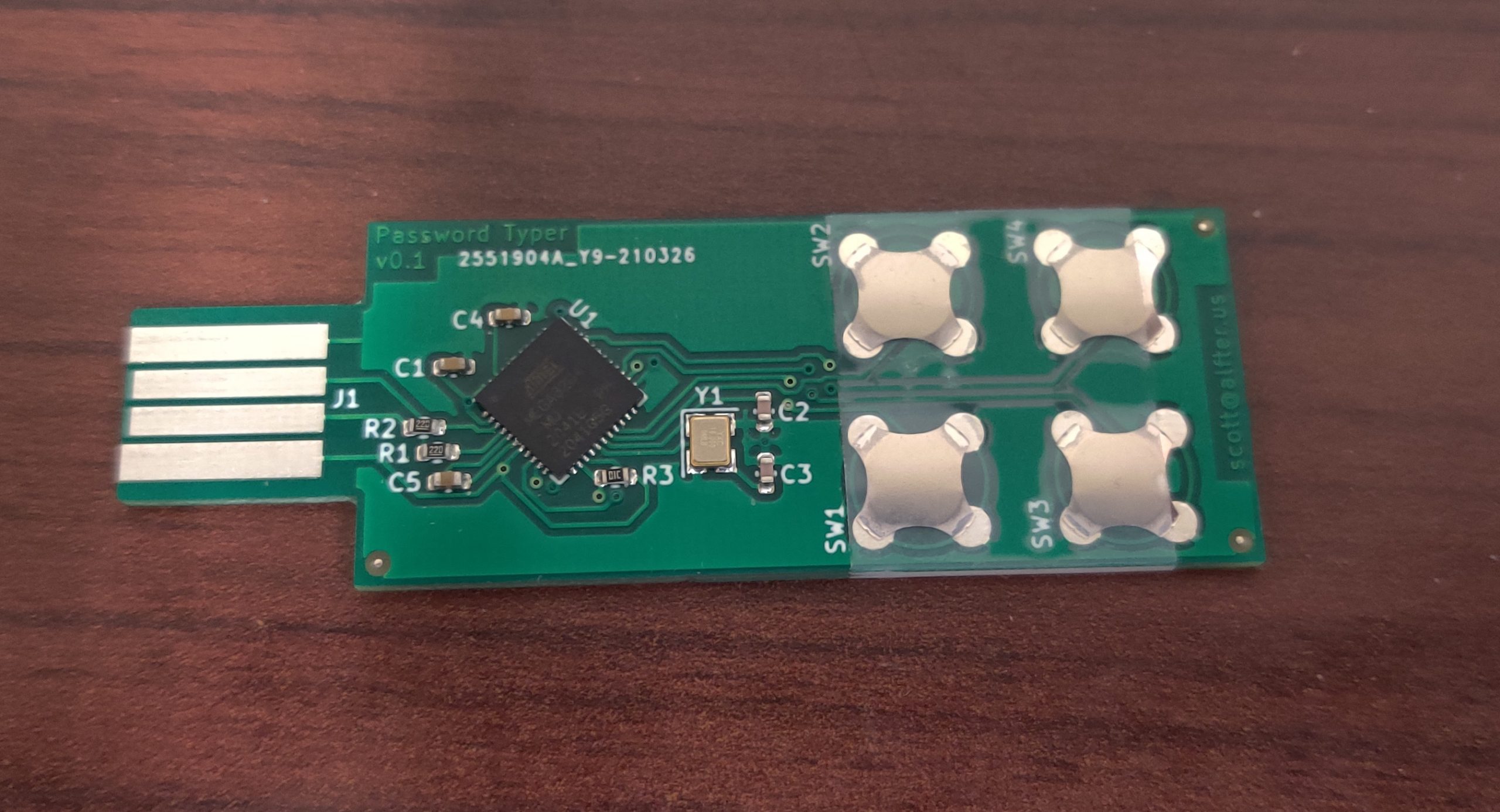
It doesn’t do everything that KeePass does, but it keeps the four passwords you use most on your keychain (or will, once it’s in the 3D-printed case I’ve planned for it). It plugs into a USB port and shows up as a keyboard. It also shows up as a serial interface, through which you can set the text to be sent by each key.
In the past, I’ve ordered boards from companies that make them and stuffed them with parts myself. This time, the boards were handed off to an assembly service that put on everything except the button domes. (They’re not supposed to be soldered; a piece of tape is sufficient to keep them in place.)
Total cost for PCB fabrication and assembly? $52 for 10 pieces of bespoke electronics. The button domes add about another $2 per board, and 3D-printed cases should be about a quarter each.
It’s amazing times we live in that such things are possible. :)
A while back, I picked up a cheap Chinese knockoff of a usbASP programmer from Amazon…originally, it was to replace the crummy factory-installed firmware on the Anet A8 motherboard with Marlin. The programmer did its job at the time and was forgotten about for a while. (The A8’s motherboard, meanwhile, crapped the bed after I had only had the printer up and running for maybe a month. It’s long since been rebuilt into an AM8 and the electronics have likewise been through several upgrades, most recently to an SKR 1.4 Turbo with TMC5160 drivers just this past weekend…but that’s getting offtopic.)
I pulled the programmer out again to try configuring some ATMEGA328s for a project. They’re empty chips ordered from DigiKey a while back, and I figured I’d try throwing Optiboot onto them. This should be a simple matter of popping the ATMEGA328 off of an Arduino Uno, plugging in one of the empty chips, plugging the usbASP into the Arduino’s ICSP header, and invoking avrdude with the right options…right?
The programmer wasn’t having any of that. With the preprogrammed chip in the Arduino, avrdude identified the chip, read out the fuses, etc. With an empty chip, it wouldn’t read out the chip ID properly. It said something about not being able to set the clock speed and that an upgrade might fix it.
The homepage for the usbASP had some firmware images, so I grabbed the newest and flashed it according to these instructions. The clock-speed error was gone, but it still wouldn’t work. I tried swapping in other Arduinos and still had no luck.
A bit of poking around led me to this fork of the usbASP firmware, last updated just nine days ago. (By comparison, the “update” I had previously applied was already ten years old!) I burned that to the usbASP, popped an empty chip back into the Arduino Uno, and fired up avrdude. Success! I burned Optiboot, set the fuses, and switched cabling on the Arduino so it was connected with just a USB cable (as usual) instead of the usbASP. The Arduino IDE saw it; I was able to send the “blinky” example to it and get the onboard LED blinking.
I was also able to diddle the fuse settings to change speeds from 16 MHz down to as low as 1 MHz and to run off the internal oscillator instead of an external crystal. I have a stepper-motor tester I started building a while back that was stalled when I think I misprogrammed the fuses and switched it to crystal operation in a circuit with no crystal. Now that the programmer is properly sorted out, I think it’s time to dig up the parts and finish this project.
I did some reading recently on design for manufacture (in particular, https://rheingoldheavy.com/design-assembly-kicad/), and one of the things that came up was that you should have your component footprints oriented the same way as they’re loaded into the tape that gets loaded into the pick-and-place machine. Many KiCad footprints (including those that ship with KiCad) aren’t oriented this way, and even in the new KiCad 5, I don’t see an easy way to rotate an entire footprint. You can rotate a footprint inside a PCB design, but unless I’m missing something, there’s no option within the footprint editor to take all the elements within and rotate them (let alone an option to rotate an individual element, as far as I can see).
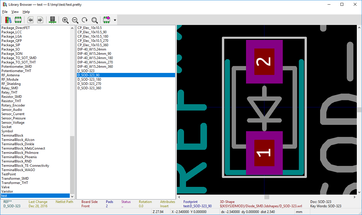
This sed script takes a KiCad footprint and rotates it 90° counterclockwise by transforming coordinates, dimensions, and rotation angles within. If you need to rotate 180°, run your footprint through the script twice. To rotate 90° clockwise, run it through three times.
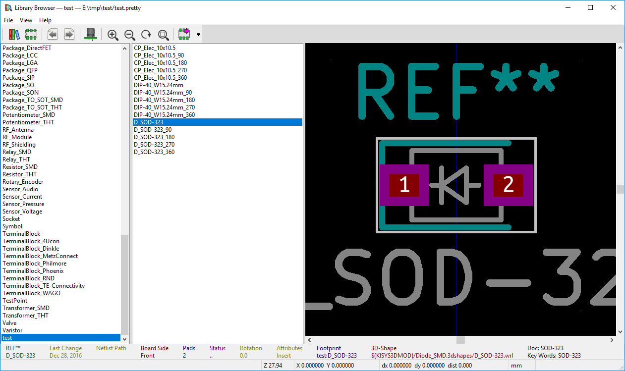
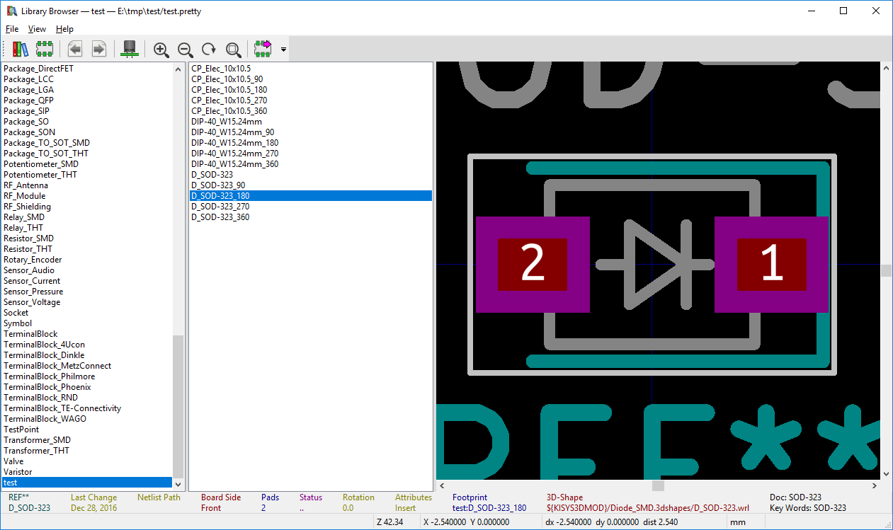
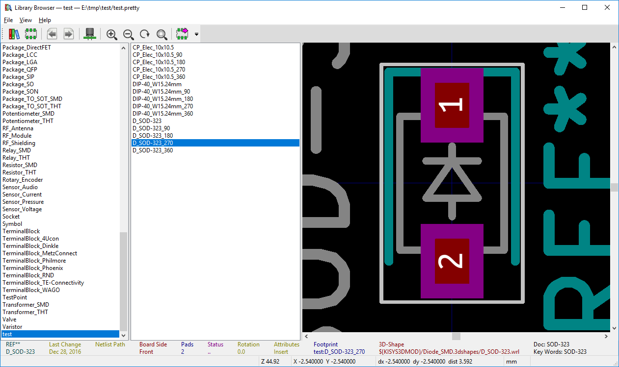
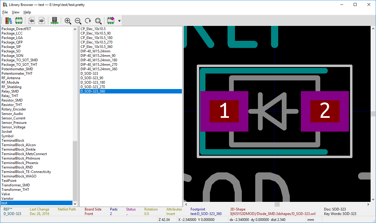
Here’s what KiCad’s SOD-323 footprint looks like as it’s rotated through 360°:
the original footprint
rotated 90°
rotated 180°
rotated 270°…this is probably how it’s loaded into the tape
rotated 360°…back where we started
I’ve tested it on a few footprints that use different types of elements, and I think it’s working properly. That said, it’d be prudent to verify that the rotated footprint is correct before you whack it into your next project. If you run across a footprint that it screws up, I would be interested in seeing it.
It’s basically a mashup of the Rocket Scream reflow oven controller shield with an Arduino Leonardo, crammed into as small a board as possible (only 2″x2.5″) so it can be installed inside nearly any toaster oven. I fired off a parts order just a few minutes ago. While the board design is ready, I like to have the parts in hand so I can verify against a printout of the board design that they’ll fit. I’ve ordered boards made before, only to find out that the parts intended to go on them wouldn’t fit.
Beyond the board and parts, the only other components I’ll still need to get are a solid-state relay (and heatsink) and a thermocouple. I think I’ll stash an iPhone charger inside to power the controller board, as I have several of them kicking around here. I already have the toaster oven…picked up one of these, as others have had success with it in their builds. It’s cheap and heats up quickly.