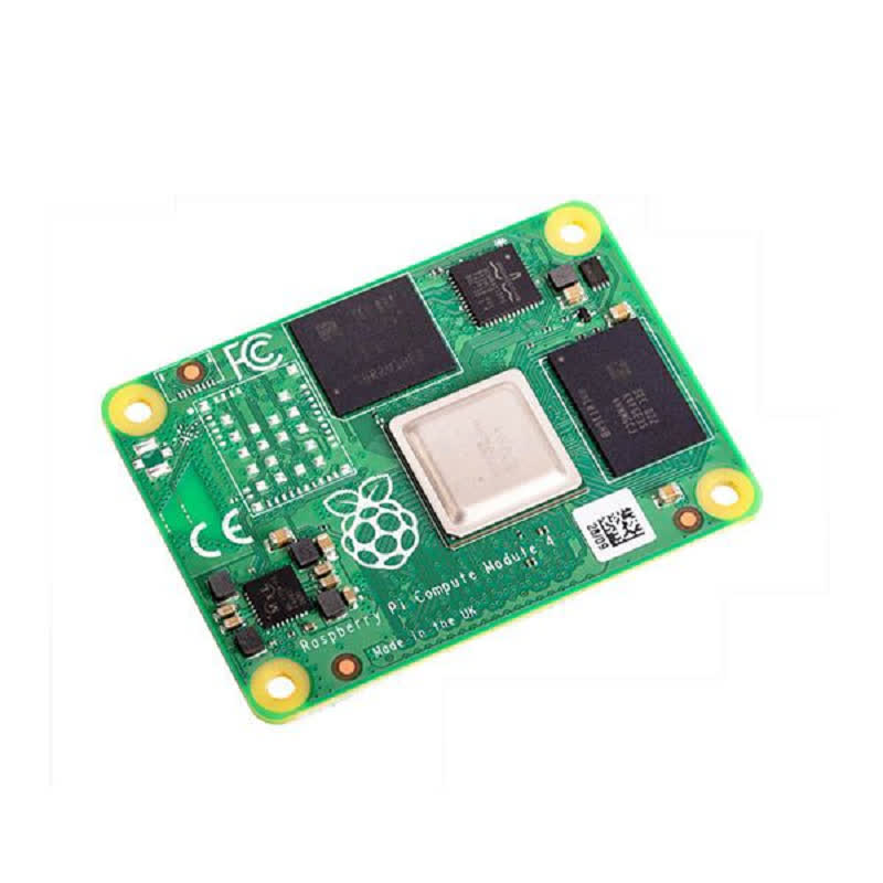
A little while back, I ran across this page about a couple of boards that turn a Raspberry Pi Compute Module 4 into a router. I’ve been running an Asus RT-AC56U for a while now and had been mulling over some upgrade options, and this sounded like a decent way to get OpenWRT back on my network. (I’d previously used it years ago on a Linksys WRT54GL, the OG router for which OpenWRT was originally developed, but never got around to running it on the newer router because there’s no support for 802.11ac on its Broadcom WiFi hardware.)
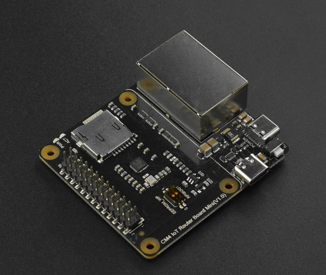
Of the two options presented, I picked the DFRobot IoT Router Carrier Board Mini because its second Ethernet port is connected directly to the CM4’s PCI Express port. (The other option inserted a USB 3.0 interface in between the two.) Nobody on this side of the pond had these in stock, but The Pi Hut had them available and shipping from the UK to the US didn’t take too long. (As I write this, they’re out of stock on all varieties of the Compute Module 4, so you’ll need to look around a bit to see if anybody has them at a not ridiculously marked-up price.)
I wanted to put stock OpenWRT on it, but the image they provide is missing the Realtek 8169 modules needed to get the second Ethernet port on the carrier board working. DFRobot provides an image with the needed modules already installed, but it’s of a 21.02 prelease. I tried upgrading it to 21.02 final, but it wouldn’t accept it.
Through a bit of trial and error, I figured out the modules I needed to add to the stock image. They could be put on there while the stack was connected to my computer to flash the firmware. Once that was done, I extracted the OpenWRT configuration from the DFRobot image and copied it over as well. With all of that in place, it now boots up with the LAN interface on the PCIe Realtek interface (the one closer to the USB-C power connector) and the WAN interface on the CM4’s Broadcom interface (the other one). Getting it working was something like what follows. (Note: I bought a CM4 with onboard eMMC; the instructions reflect this. If you bought one without, you’ll need to write the firmware to a MicroSD card, which might actually be a bit easier to set up in hindsight. I wanted fewer parts, though, and I think eMMC is supposed to be a little bit faster. Also, these instructions assume you’re using Linux. Mac OS X might be slightly different. Windows will probably be considerably different, and an attempt at accessing the eMMC from Windows 10 according to DFRobot’s instructions failed.)
- Plug the CM4 into the carrier board. Be careful and make sure the two 100-pin connectors are properly aligned.
- Download the OpenWRT 21.02 release image and decompress it.
- Check out the Raspberry Pi usbboot tool and build it:
git clone --depth=1 https://github.com/raspberrypi/usbboot && cd usbboot && make
(note: you need libusb to build and use this) - Peel the protective tape off of the switch block and use a small pointy object to flip the “USBBOOT” switch on (toward the MicroSD slot).
- Plug a USB A-to-C cable into the carrier’s port labeled “USB.” Plug a USB-C power supply into the port labeled “POWER.”
- Bring up the CM4 as a storage device:
sudo ./rpiboot. Determine which device node it grabbed (dmesgis good for this); in my case, it was /dev/sda. - Flash the OpenWRT image:
dd if=openwrt-21.02.0-bcm27xx-bcm2711-rpi-4-ext4-factory.img of=/dev/sda bs=512 status=progress - Resize /dev/sda2 to take up the rest of the storage space;
gpartedis a good tool for this. - Mount /dev/sda2 someplace (I used /mnt/usbdisk as it was already there and not in use) and create a new directory:
sudo mkdir /mnt/usbdisk/ipks - Download these OpenWRT packages to get the Realtek 8169 working: r8169-firmware kmod-mii kmod-libphy kmod-phy-realtek kmod-r8169. Save them to /mnt/usbdisk/ipks.
- Download and uncompress the DFRobot prerelease image; we need to extract its config files.
- We need to find the start of the root partition within the image, so
sudo gparted openwrt-bcm27xx-bcm2711-rpi-4-ext4-factory.img, right-click on the second partition, and click Information. Scroll up in the window that pops up to get the location of the first sector; for the image I downloaded, it was 147456. Multiplying this by 512 (the block size in bytes), we get 75497472; keep this number in mind. Close gparted. - Mount the root partition and copy the config files over to the CM4:
sudo mount -o loop,ro,offset=75497472 openwrt-bcm27xx-bcm2711-rpi-4-ext4-factory.img /mnt/tmp && sudo cp /mnt/tmp/etc/config/* /mnt/usbdisk/etc/config/ sudo umount /mnt/usbdisk && sudo umount /mnt/tmp, and unplug the cables from the carrier board.- Plug a USB-to-TTL-serial cable into the carrier board’s GPIO header: black to pin 6, white to pin 8, green to pin 10. Leave the red wire disconnected. Plug the USB end into your computer and note which device node it grabs (probably /dev/ttyUSB0). Fire up your favorite comm program (Minicom, perhaps?) on that port at 115.2 kbps:
minicom -D /dev/ttyUSB0 -b 115200 - Plug the USB-C power supply back into the “POWER” connector. Watch the boot messages scroll by for a few seconds, and press Enter to get a root prompt in OpenWRT.
- Install the modules we stored in /ipks:
cd /ipks && for i in r8169-firmware_20201118-3_aarch64_cortex-a72.ipk kmod-libphy_5.4.143-1_aarch64_cortex-a72.ipk kmod-phy-realtek_5.4.143-1_aarch64_cortex-a72.ipk kmod-mii_5.4.143-1_aarch64_cortex-a72.ipk r8169-firmware_20201118-3_aarch64_cortex-a72.ipk; do opkg install $i; done - Shut down OpenWRT:
poweroff. Wait for the green LED to quit blinking. Unplug the power and flip the USBBOOT switch back to “off” (away from the MicroSD slot). - Disconnect the serial cable and run a network cable from the LAN port (the one closer to the power connector) to your computer. Plug the power back in, wait a few seconds for it to boot, and go to https://192.168.1.1; it should bring up OpenWRT’s LuCI interface. You’re done! Configure OpenWRT to your liking, then move it closer to your network gear and run cables from the LAN port to an empty switch port and from the WAN port to whatever provides your Internet (cable modem, DSL modem, or whatever).
All that’s left now is to put it in a case (either 3D-printed, or maybe just the laser-cut case from DFRobot) and add a wireless access point. I’ve had good luck with a bunch of Cisco WAP150s at work, but I’m open to suggestions. (I could’ve gotten one of the WiFi-equipped CM4s, but my understanding is that since they’re connected over SPI to the CM4’s SoC, their speed is not so good.)